Step 2
Separate sensor housings.
Insert small screwdriver into slot in bottom and push
up on latch. Then gently pull the housings apart at
the base.
Corner Mount
Knockouts
Wall Mount
Knockouts
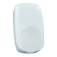
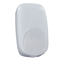
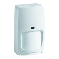
DT-500 Series Animal Immune DUAL TEC
®
Motion Sensor Installation Instructions
Step 1
Select the mounting location.
Mount at 7'6" / 2.3 m for optimal animal
immunity.
Step 5
Wire the sensor.
Observing the proper polarity, wire the unit as
shown (use 14-22 AWG). Push as much wire as
possible back into the wall when returning the PCB
to its housing.
Step 6
Walk-test the sensor.
Apply power to the sensor and let it warm up for
three minutes. Begin walk-test after the red LED
has stopped flashing.
Step 3
Remove the PCB.
Push down on the latch at the bottom of the
housing. Then gently pull the printed circuit board
(PCB) forward and up by the terminal strip.
Step 4
Mount the sensor.
Carefully break out appropriate mounting knock-
outs on the rear housing, and mount it in the
desired location.
Walk across the protected area at the ranges to
be covered. The red LED will indicate an alarm
condition after two to four normal steps. When
there is no motion in the protected area, the LED
will be off.
Wiring Hole
Aim the DT-500/DT-500T
away from:
NOTE: For proper wiring methods, refer to the National
Electrical Code NFPA 70.
WARNING: DO NOT touch the antenna when removing
the PCB from the rear housing.
Antenna
Red Alarm LED
W1 (Cut W1 Wire to
Disable LED)
Model DT-500T Only
Model DT-500T Only