Home
Honeywell
Measuring Instruments
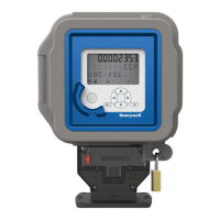
EC350
Honeywell EC350 User Manual
4
of 1
of 1 rating
249 pages
Give review
Manual
Specs
To Next Page
To Next Page
Loading...
EC350
User
Manual
FD-583
|
V1.6
|
2024
Honeywell
Process
Solutions
Mercury
Instruments,
2101
Citywest
Boulevard
Houston,
TX
77042
USA
855
251-7065
–
United
States
&
Canada
302
669-4253
–
Outside
the
United
States
https://process.honeywell.com
EC350
2
Table of Contents
1 About EC350
10
1.1 EC350 specifications
11
1.1.1 Certifications
11
1.1.2 Power
11
1.1.3 Environmental
12
1.1.4 Temperature measurement
12
1.1.5 Pressure measurement
13
1.1.6 API 21.1 compliance
13
1.2 Safety instructions
14
1.2.1 Things to remember
15
1.2.1.1 Usage of EC350 in hazardous areas
15
1.2.1.2 Service, maintenance, and troubleshooting EC350
17
1.2.1.3 FCC: Part 15 B Class-A Digital device
17
1.3 Theory of Operation
19
1.3.1 Correction Factors to Metered Volume
19
1.3.2 Pressure Factor Fp
20
1.3.3 Temperature Factor Ft
20
1.3.4 Supercompressibiity Factor Fpv
20
1.4 Main interfaces of EC350
22
1.4.1 LCD
22
1.4.2 Keypad
23
1.4.3 External Connections
24
2 Security Guidelines
25
2.1 Device Security Recommendations
26
2.2 Implementing stringent password guidelines
27
2.3 How to report a security vulnerability
28
2.4 Preventing unauthorized external access using a firewall
29
3 EC350 installation
30
3.1 EC350 contents verification
31
3.2 Overview of installation
32
3.3 Model number interpretation
34
3.4 Prerequisites
34
3.5 Installing EC350 on conventional diaphragm, rotary or turbine gas meters
35
3.5.1 Installing the index slide and label
35
3.5.1.1 Next steps
36
3.5.2 Changing the drive rotation
37
3.5.3 Mounting EC350 on the meter
38
3.5.4 Connecting a pressure line to EC350
39
3.6 Installing EC350 on a rotary mount
40
3.6.1 Selecting the mounting orientation
40
3.6.2 Installing the temperature probe
41
3.6.3 Connecting a pressure line to the EC350
42
3.6.4 Installing EC350 on rotary mounts
43
3.7 Power Supply Options
51
3.7.1 External Power Supply
51
3.7.2 Battery Powered
52
3.8 General Wiring connections
53
3.8.1 Pulse output communication
53
3.8.2 Pulse output specification
56
3.8.3 Pulse outputs via the case connector option
58
3.9 Installation Drawings
59
4 Securing the device
62
4.1 Case
63
4.2 Metrological protection modes
63
4.2.1 Item classifications
63
4.2.2 Access restriction Item 139 configuration options
64
4.2.3 Event log full note
64
4.2.4 Changing item 139
65
4.3 Defining access privileges
66
4.3.1 Default User Table
66
4.3.2 Creating a user table file
67
4.3.3 Sending a user table file
69
4.4 Metrological configuration mode
71
4.5 Validating setup configuration
72
5 Key features
73
5.1 Volume measurement
74
5.1.1 Corrected volume
74
5.1.2 Uncorrected volume
75
5.1.3 Energy
75
5.1.4 Volume statistics
75
5.1.5 Volume Input Modes
75
5.1.5.1 UMB, Instrument Drive & Remote input
75
5.1.5.2 Direct Rotary mount input
76
5.1.5.3 Bidirectional volume or Reverse flow
76
5.1.6 Volume switch filtering
78
5.1.7 Digital switch inputs
78
5.2 P-T-Z Measurement
79
5.2.1 Gas Pressure
79
5.2.1.1 Gas Pressure statistics
79
5.2.1.2 Fixed Gas pressure
81
5.2.2 Gas Temperature
82
5.2.2.1 Temperature statistics
82
5.2.2.2 Fixed Gas temperature
83
5.2.3 Supercompressibility
83
5.2.3.1 Supercompressibility Factor
83
5.2.3.2 Item Description for Supercompressibility factors
85
5.3 Meter proving
87
5.3.1 Connecting the USB cable to the prover dongle
88
5.3.1.1 Cable adapter for the SNAP prover system
88
5.3.2 Proving dongle indicators
89
5.3.2.1 Proving dongle
89
5.3.3 Starting Pushbutton proving
90
5.3.3.1 Entering Pushbutton Proving mode
90
5.3.4 Volume per proving output pulse
92
5.4 Alarms
96
5.5 Logging
100
5.5.1 Audit Trail Logging Configuration
100
5.5.2 Reading Audit Trail from the EC350
104
5.5.2.1 Displaying/Viewing Audit Trail reports
105
5.5.3 Event logger
105
5.5.3.1 Supported Event Codes
106
5.5.3.2 Clearing Event Log
106
5.5.4 Log record integrity verification
107
5.6 Battery Life/ Usage Tracking
108
5.7 Display ON/OFF
109
6 User Access
110
6.1 Getting started with the keypad
111
6.1.1 Unlocking the keypad
111
6.1.2 Human Machine Interface (HMI)
111
6.1.2.1 Level 0 mode
112
6.1.2.2 Level 1 mode
113
6.1.2.3 Level 2 mode
130
6.1.2.4 Level 3 mode
143
6.2 Working with HMI
152
6.2.1 Choosing the meter type
152
6.2.2 Verifying pressure
154
6.2.3 Verifying temperature
156
6.2.4 Testing the pulse input
158
6.2.5 Entering the site ID
159
6.2.6 Setting the date and time
160
6.2.6.1 Setting the date
160
6.2.6.2 Setting the time
161
6.2.6.3 Auto set date and time
162
6.2.7 Selecting the unit of measure
163
6.2.7.1 Selecting the unit of measurement for volume
164
6.2.7.2 Selecting the unit of measurement for energy
166
6.2.7.3 Selecting the unit of measurement for pressure
168
6.2.7.4 Selecting the unit of measurement for temperature
170
6.2.8 Single point temperature and pressure calibration
172
6.2.8.1 Calibrating temperature
172
6.2.8.2 Calibrating pressure
173
6.3 Connecting to EC350 via MasterLink Software Application R610
175
6.3.1 About MasterLink Software Application R610
175
6.3.2 Connecting the IrDA communication USB dongle to the computer
175
6.3.3 Connecting the IrDA communication USB dongle to EC350
175
6.3.4 Signing on to the EC350
176
6.3.5 Updating EC350 firmware
177
6.3.5.1 Application Firmware
178
6.3.5.2 Key File
179
6.3.5.3 BootLoader Firmware
181
6.3.6 Force schedule Call-In Time After FW Update
184
6.3.7 Troubleshooting scenarios
185
6.4 Working with MasterLink Software Application SQL
186
6.4.1 Items by function
186
6.4.2 Setting time and date
187
6.4.3 Item files
187
6.4.3.1 Reading/Creating item files
187
6.4.3.2 Displaying/Viewing item files
188
6.4.4 Calibrating pressure
188
6.4.5 Calibrating PLog pressure
190
6.4.6 Calibrating temperature
192
6.4.7 Configuring the Meter reader list
194
6.4.8 Configuring Call in feature
195
6.5 Working with PowerSpring
200
6.5.1 Adding EC350 to PowerSpring
200
6.5.2 Configure EC350 in PowerSpring
202
6.6 Connecting EC350 with PowerSpring using a Messenger Modem
220
6.6.1 Configure EC350 using MasterLink Software Application
220
7 Remote Communications
224
7.1 Use of RS232/RS485/UART
225
7.2 Call in and call out
227
7.2.1 Call in
227
7.2.1.1 Call in
227
7.2.1.2 Scheduled Call In
228
7.2.1.3 Alarm Call In
229
7.2.1.4 Force schedule Call
229
7.2.1.5 Management of Multiple Phone Numbers
229
7.2.1.6 Retry Timing
230
7.2.1.7 LCD indications
230
7.2.1.8 Forcing a Test Call
231
7.2.2 Call out
231
7.2.2.1 Set Call Out time
231
7.2.2.2 Set a call out stop time
232
7.3 Modbus Communication
234
8 Maintenance
236
8.1 Temperature Probe Measurement Kits
236
8.2 Transducer Replacement Kits
239
8.3 Redundant Uncorrected Switch
240
8.4 Metrological Sealing Cover (MC)
240
8.5 Removing and Re-Installing Modem Mounting Plate
242
8.6 Replacing the Battery Pack
243
8.6.1 Replacing the battery in a hazardous DIV-1/ZONE-0 environment
243
8.6.2 Replacing the battery in a non-hazardous environment
243
8.7 Low battery/ External Power shutdown mode
245
8.8 User Shelf/ Shutdown mode
247
8.8.1 To enter user shutdown mode using HMI mode 2 or 3
247
8.8.2 To enter user shutdown mode using MasterLink Software Application SQL
247
4
Based on 1 rating
Ask a question
Give review
Questions and Answers:
Need help?
Do you have a question about the Honeywell EC350 and is the answer not in the manual?
Ask a question
Honeywell EC350 Specifications
General
Brand
Honeywell
Model
EC350
Category
Measuring Instruments
Language
English
Related product manuals
Honeywell E-Mon
2 pages
Honeywell RMA300-EU
36 pages
Honeywell Enraf 977
28 pages
Honeywell ENCAL 3000
141 pages
Honeywell Enraf 854 ATG
24 pages
Honeywell Envitec MySignO
44 pages
Honeywell E-Mon Class 6200
84 pages
Honeywell E-Mon Class 3200
44 pages
Honeywell E-Mon EM3S-V-P-R
84 pages
Honeywell eZtrend GR Series
4 pages
Honeywell AS302P
92 pages
Honeywell BK-G1.6A
14 pages