13 32-00156-03
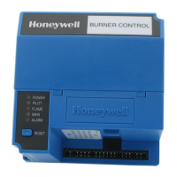
RM7895A,B,C,D/EC7895A,C; RM7896A,C,D7800 SERIES Relay Modules
Run/Test Switch (RM/EC7895C,D; RM7896C,D only)
The Run/Test Switch is located on the top side of the relay
module, see Fig. 5. The Run/Test Switch allows the burner se-
quence to be altered as follows:
1. In the measured PREPURGE sequence, the Run/Test
Switch, placed in the TEST position, causes the PRE-
PURGE timing to stop.
2. In the Pilot Flame Establishing Period, the Run/Test
Switch, placed in the TEST position, stops the timer during
the first eight seconds of a ten-second PFEP selection or
during the first three seconds of a foursecond PFEP selec-
tion. It also allows for pilot turndown test and other burner
adjustments. This activates a fifteen-second flameout tim-
er that permits pilot flame adjustment without nuisance
safety shutdowns. The Run/Test Switch is ignored during
PFEP for the C and D relay modules if terminals 8 and 9 or
9 and 21 are jumpered.
IMPORTANT
When the relay module is switched to the TEST mode, it stops
and holds at the next Run/Test Switch point in the operating
sequence. Make sure that the Run/Test Switch is in the RUN
position before leaving the installation.
SEQUENCE
STATUS
LEDs
RESET
PUSHBUTTO
N
FLAME
SIMULATOR INPUT
FLAME CURRENT
TEST JACKS
CAPTIVE
MOUNTING
SCREW
DUST
COVER
RELAY
MODULE
FLAM
PURGE
CARD
Fig. 5. Sequence Status LEDs.
SETTINGS AND ADJUSTMENTS
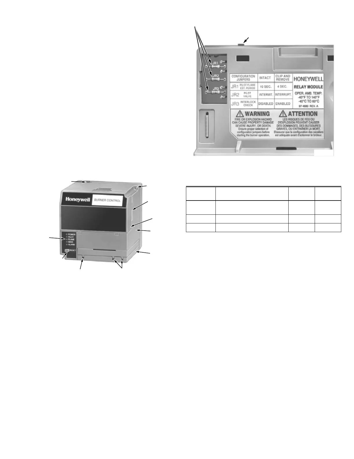
Selectable Site-Configurable Jumpers
The relay module has three site-configurable jumper options,
see Fig. 6 and Table 6. If necessary, clip the siteconfigurable
jumpers with side cutters and remove the resistors from the
relay module.
SERVICE NOTE: Clipping and removing a site-
configurable jumper enhances the level of safety.
M7553A
SELECTABLE CONFIGURATION JUMPERS
RUNTEST SWITCH
(EC7895C; RM7895C,D; RM7896C,D)
Fig. 6. Selectable site-configurable jumpers.
Table 7. Site-configurable jumper options.
Jumper
Number
Description Intact Clipped
JR1
a, b
Pilot Flame Establishing
Period (PFEP)
10
seconds
4
seconds
JR2
c
Flame Failure Action Recycle Lockout
JR3 Airflow Switch (ILK) Failure Recycle Lockout
a The RM7895C1020/2020 and RM7896C1036/2036 have fixed
PFEP of ten seconds and do not have jumper JR1.
b The RM7895C1053/2053 has fixed PFEP of four seconds and
does not have jumper JR1.
c The RM7895C1053/2053 locks out on Flame Failure Action and
does not have jumper JR2.
IMPORTANT
Clipping and removing a jumper after 200 hours of operation
causes a nonresettable Fault 110. The relay module must
then be replaced.
SAFETY AND SECURITY
Physical device protection
Device shall be accessible to authorized personnel only – In-
stallation on publicly accessible places is not recommended
as this could lead to unwanted and potentially unsafe chang-
es to device (wiring, configuration, etc).
It is recommended to lock the device in an enclosed cabinet
with access allowed only to approved and trained person-
nel. Also, it is strongly advised to keep all the wiring of device
physically secure.
Physical protection of the device is applied via Run/Test
switch label/seal. It is intended to prevent and detect unau-
thorized access.
 Loading...