DISTRIBUTED I/O – PRODUCT DATA
3 EN0B-0090GE51 R0316
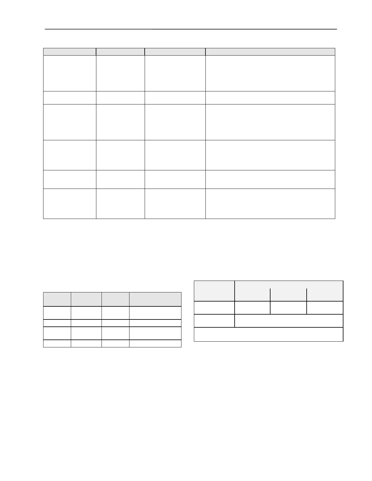
Table 3. Node Object network variables
NV name type range description
nviRequest SNVT_obj_request
RQ_NORMAL
RQ_DISABLE
RQ_ENABLE
RQ_UPDATE_STATUS
RQ_REPOPRT_MASK
RQ_SELF_TEST
Upon receiving an update to nviRequest, nvoStatus is
updated.
RQ_SELF_TEST is used only in the XFL522B analog
output module for outputs configured as a motor. In this
case, a synchronization is performed to set the actuator
in the 0% position.
nvoStatus SNVT_obj_status
Reports the status of the node upon request through
nviRequest.
nciNetConfig SNVT_config_src
CFG_LOCAL (default)
CFG_EXTERNAL
This configuration variable is set to CFG_LOCAL at the
factory and whenever the rotary HEX switch is reset. If
it is set to CFG_EXTERNAL, a network manager will
assign a network address for the node. In this case, the
module will not modify its location string as long as the
rotary HEX switch is not reset.
nvoFileDirectory SNVT_address
Points to a file directory in the address space of the
Neuron® chip containing descriptors for the files in the
module. It is used to access the configuration pro-
perties stored in configuration parameter files accessed
by network management read/write messages.
SCPTMinSendTime SNVT_time_sec
1.0 to 10.0 sec
(default = 1.0 sec)
Defines the min. period of time between output variable
transitions. This configuration property is applicable
only to output NVs of the input modules.
SCPTMaxSendTime SNVT_time_sec
1.0 to 6553.4 sec
(default = 60.0 sec)
Defines the max. time period of time before output NVs
are automatically updated. It must be set to a higher
number than SCPTminSendTime. This configuration
property is applicable only to output NVs of the input
modules.
XFL52xB Module Response Times
The response time of Distributed I/O modules is defined as
the period of time between the updating of the physical signal
and the updating of the NV (or vice versa). The response time
varies somewhat due to certain factors and is also dependent
upon the module type (see also Table 4).
Table 4. Response time (RT)
module
typical RT
(sec)
max. RT
(sec)
min. time between
2 updates
XFL521B 0.8 1.6
SNVTMinSendTime
(default: 1 sec)
XFL522B 0.2 0.4 n.a.
XFL523B 0.3 0.5
SNVTMinSendTime
(default: 1 sec)
XFL524B 0.2 0.4 not applicable
XSL511 Connector Module Power Supply
NOTE: When connecting XFL52xB modules to the power
supply, the same side of the transformer must
always be connected to the same side of the
XSL511 (see also Fig. 11 on page 9)!
Cable Lengths and Cross Sectional Areas
Distribute I/O cables must meet the same requirements
specified for Excel 500 and Excel 600 I/O as specified in
Table 5.
Table 5. Cable sizing.
type of signal
cross sectional area
300 ft
(100 m)
550 ft
(170 m)
1300 ft
(400 m)
24 Vac power
supply
16 AWG
( 1.5 mm
2
)
14 AWG
( 2.5 mm
2
)
-
Low voltage
signals
1
20 AWG ( 0.5 mm
2
)
1
0...10 V sensors, totalizers, digital inputs, 0...10 V signals for
actuators, etc.
IMPORTANT
The max. length of a signal cable with 24 Vac supply is
550 ft (170 m).
The max. length of a two-wire, 0 to 10 Vdc signal
cable is 1300 ft (400 m).
The secondary side of the transformer must not be
connected to earth ground.

 Loading...


