69-1150—2
8
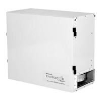
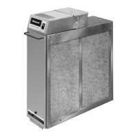
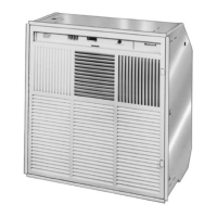
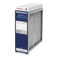
F50F DUCT MOUNTED ELECTRONIC AIR CLEANER
M5676A
3
1
2
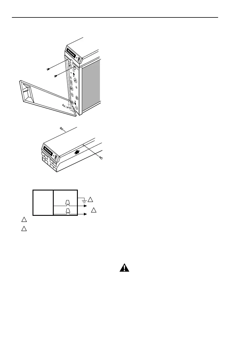
REMOVING COVER FROM POWER BOX.
ELECTRONIC
AIR CLEANER
WIRING
COMPARTMENT
BLACK
BROWN
POWER SUPPLY. PROVIDE DISCONNECT MEANS AND
OVERLOAD PROTECTION AS REQUIRED.
THE AIR CLEANER CAN BE COMPLETELY ISOLATED FROM
THE ELECTRICAL CIRCUIT OF THE HVAC SYSTEM UNLESS
REQUIRED BY LOCAL CODE TO USE SAME CIRCUIT. ANY
CONVENIENT HOUSE CIRCUIT CAN POWER AIR CLEANER,
REGARDLESS OF ELECTRICAL RATING OF HVAC SYSTEM.
M5707
2
1
2
L1 (HOT)
L2
1
Fig. 13. Removing cover from power box.
Fig. 14. Conduit connection for F50F
(Not applicable in European countries).
OPERATION
Large particles (lint, hair) are caught by the prefilter. As the
dirty air passes through the intense high voltage electric
field surrounding the ionizer wires, all particles are given
an electrical charge. The air then moves through the
collector part of the cell where alternate parallel plates are
charged positively and negatively, creating a uniform
electrostatic field. The charged particles are attracted to
and collect on the plates having the opposite electrical
charge. The air leaving the air cleaner has fewer particles.
Each time the air circulates through the F50F, more
particles are removed.
CHECKOUT
Inspect Installation
Make sure:
• Turning vanes and transitions, as needed, are properly
installed.
• Sheet metal joints between air cleaner and furnace are
sealed.
• All sheet metal connections are complete.
• Original furnace filter has been removed and the blower
compartment cleaned.
• If an atomizing humidifier is installed upstream from the
air cleaner, a disposable furnace filter is installed
between the humidifier and the air cleaner.
• Outside air, if used, is mixed with return air or heated,
as necessary, before it can reach the air cleaner.
• The airflow arrows on the electronic cell point down-
stream.
• The prefilter is on the upstream side of the cell.
• The cell handle faces outward.
• The electronic cell and prefilter are clean and dry.
• Wiring connections to the W8600F (optional) are
properly made.
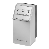
Check Air Cleaner Operation
With all components in place, turn on the air cleaner switch
and energize the system blower. Check the following
points of operation:
1. The neon light next to the on-off switch is on. If a
W8600F is part of the installation, also check the
wall panel and make sure ON is indicated. The
W8600F FAULT will come on if there is a problem
with the high voltage power supply.
2. Turn off the system blower. The neon light should go
off after a few seconds. The neon light shows that
the air cleaner is energized and the high voltage
power supply is working properly.
3. Turn on the system blower. With the air cleaner
energized, push the test button. A snapping sound
indicates that the collector voltage is present on the
cell. On air cleaner with a W8600F, the FAULT
indicator will come on when the test button is held
down.
4. With a multispeed blower, repeat steps 1-3 for each
fan speed.
5. If operation is not as described, refer to the Trouble-
shooting and Service section.
TROUBLESHOOTING AND SERVICE
WARNING
Electric Shock Hazard.
Can cause personal injury
or equipment damage.
The following procedures expose hazardous live
parts. Disconnect from power between checks and
proceed carefully. The instructions are for use by
qualified personnel only.
 Loading...