8
GENERATOR CONNECTIONS
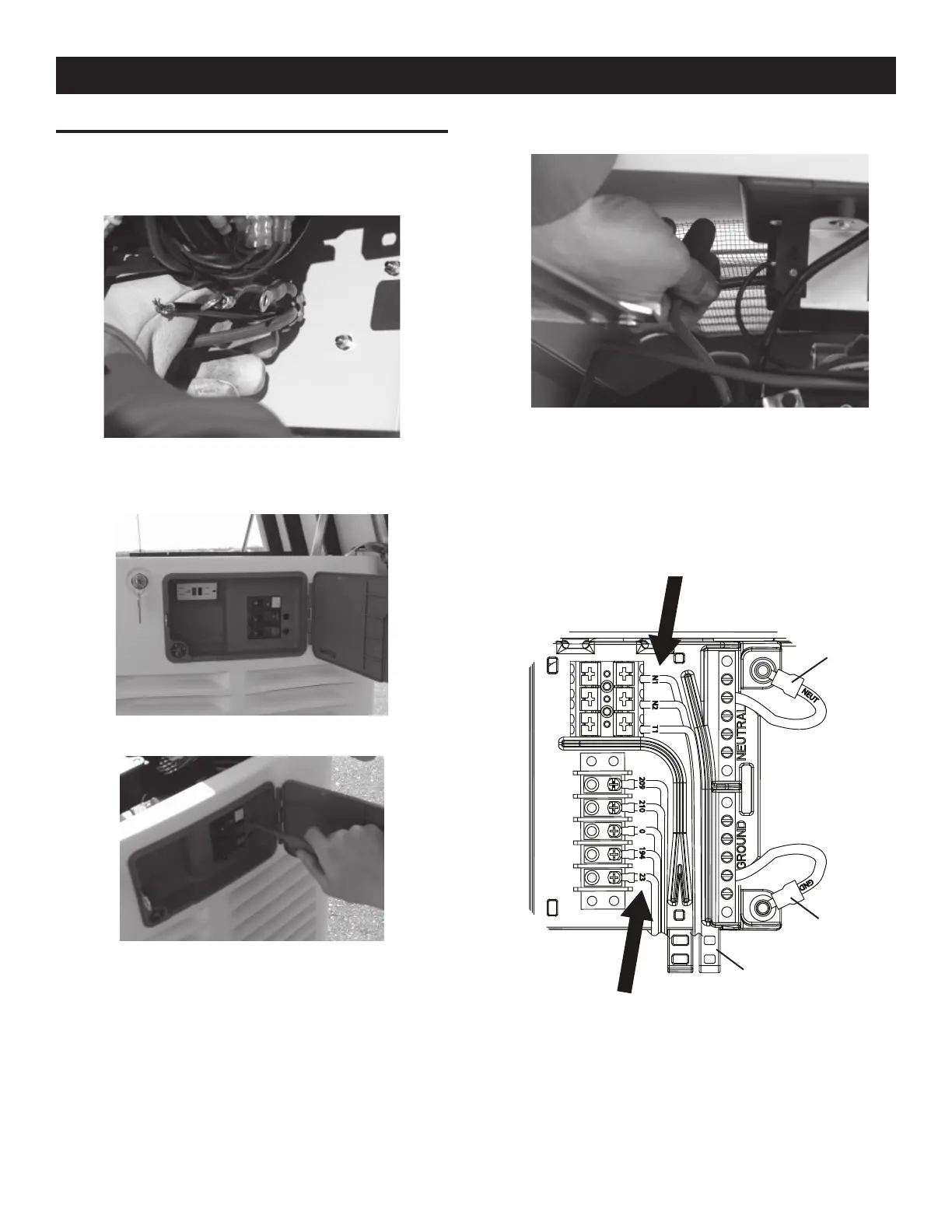
1. Remove the two screws securing the connection area cover,
and remove the cover.
2. Feed the wires through the back of the generator and secure
the conduit with the lock nut.
3. Run the power leads through the strain relief provided.
4. The circuit breaker is attached to the exterior access panel.
5. Remove the plastic plugs inside the main breaker access area
to allow connection of the power leads to the circuit breaker.
6. Now connect the red and black power leads to the circuit
breaker. Since this is a single-phase application, it doesn’t
matter which wire is connected to which lug.
7. Connect the green equipment ground wire to the ground bus
bar and torque to 35 inch lbs. The torque values are:
10-14 AWG = 35 in/lbs•
8 AWG = 40 in/lbs•
4-6 AWG = 45 in/lbs•
T1
N2
N1
209
210
0
194
23
NEUT
GND
8. Connect the white neutral wire to the neutral bus bar and
torque to 35 inch lbs. The torque values are:
10-14 AWG = 35 in/lbs•
8 AWG = 40 in/lbs•
4-6 AWG = 45 in/lbs•
Neutral
Ground
Cable Tie Location
General Information
 Loading...