3. Devices are point addressable up to 159 addresses.
4. The heat sensor operates as a programmable heat detector.
NOTE: In panels where this feature is not available, the FST-951 and
FST-951-IV will default to a 135°F fixed heat detector. FST-951R and
FST-951R-IV will default to a 135°F fixed heat detector and rate-of-rise.
FST-951H and FST-951H-IV will default to a 190°F high temperature heat
detector.
Intelligent programmable temperature sensors require compatible addressable
communications to function properly. Connect these sensors to listed-compat-
ible control panels only.
WIRING GUIDE
All wiring must be installed in compliance with the National Electrical Code,
applicable local codes and the Authority Having Jurisdiction. Proper wire
gauges should be used. The installation wires should be color coded to limit
wiring mistakes and ease system troubleshooting. Improper connections will
prevent a system from responding properly in the event of a fire.
Remove power from the communication line before installing sensors.
1. Wire the sensor base (supplied separately) as shown in the wiring
diagram. (See Figure 2.)
2. Set the desired address on the rotary dial switches. (See Figure 1.).
3. Install the sensor into the sensor base. Push the sensor into the base
while turning it clockwise to secure it in place.
4. After all sensors have been installed, apply power to the control unit and
activate the communication line.
5. Test the sensor(s) as described in the TESTING section of this manual.
FIGURE 2. WIRING DIAGRAM:
2
3
1
2
3
3
1
2
1
(–)
(+)
+ -
UL Listed Compatible
Control Panel
CAUTION: Do not loop wire under
terminal 1 or 2. Break wire run to
supervise connections.
CLASS A OPTIONAL WIRING
Remote
Annunciator
(–)
(+)
RA
+
–
+
RA
+
–
+
RA
+
–
+
C0129-10
SPECIFICATIONS
Operating Voltage Range: 15 to 32 Volts DC Peak
Operating Current @ 24 VDC: 200 uA (one communication every 5 seconds with green LED blink on communication)
Maximum Alarm Current: 2 mA @ 24 VDC (one communication every 5 seconds with red LED solid on)
Maximum Current: 4.5 mA @ 24 VDC (one communication every 5 seconds with amber LED solid on)
Operating Humidity Range: 10% to 93% Relative Humidity, Non-condensing
Installation Temperature: Set for fixed-temperature or rate-of-rise (ROR): –4°F to 100°F (–20°C to 38°C)
Set for high-heat: –4°F to 150°F (–20°C to 66°C)
Fixed Temperature Rating: 135°F (57°C)
High Heat Temperature Rating: 190°F (88°C)
Rate-of Rise Detection: Responds to greater than 15°F/minute or 135°F (8.3°C/minute or 57°C)
Height: 2.0˝ (51 mm) installed in B300-6 Base
Diameter: 6.2˝ (156 mm) installed in B300-6 Base
Weight: 3.4 oz. (95 g)
UL 521 listed for Heat Detectors
This sensor must be installed in compliance with the control panel system
installation manual. The installation must meet the requirements of the Au-
thority Having Jurisdiction (AHJ). Sensors offer maximum performance when
installed in compliance with the National Fire Protection Association (NFPA);
see NFPA 72.
Before installing sensors, please read the system wiring and installation man-
ual thoroughly. This manual provides detailed information on sensor spac-
ing, placement, zoning, and special applications. Copies of these manuals are
available from Notifier.
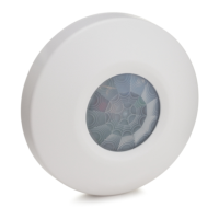
GENERAL DESCRIPTION
Models FST-951, FST-951-IV, FST-951R, FST-951R-IV, FST-951H, and
FST-951H-IV are field programmable intelligent sensors that utilize a state-of-
the-art thermistor sensing circuit for fast response. These sensors are designed
to provide open area protection with 50-foot spacing capability as approved
by UL 521. The intelligent temperature sensor can be programmed as either
a 135°F fixed temperature sensor, a rate of rise and 135°F fixed temperature
sensor or a 190°F high temperature sensor through the Fire Alarm Control
Panel (FACP).
Two LEDs on each sensor light to provide a local, visible sensor indication.
Remote LED annunciator capability is available as an optional accessory
(Part No. RA100Z). Rotary dial switches are provided for setting the sensor's
address. (See Figure 1.)
FIGURE 1: ROTARY ADDRESS SWITCHES
9
10
11
12
13
14
15
8
7
6
5
4
3
2
1
0
9
8
7
6
5
4
3
2
1
0
C0162-00
Notifier panels offer different feature sets across different models. As a result,
certain features of the Intelligent Programmable Temperature Sensors may
be available on some control panels, but not on others. FST-951, FST-951R,
and FST-951H will support only FlashScan® protocol mode. FST-951-IV,
FST-951R-IV, and FST-951H-IV will support either FlashScan or CLIP (Classic
Loop Interface Protocol) mode.
The possible features available if supported by the control panel include:
1. The sensor’s LEDs can operate in three ways—on, off, and blinking–and
they can be set to red, green, or amber. This is controlled by the panel.
2. The remote output may be synchronized to the LED operation or con-
trolled independent of the LEDs. Please refer to the operation manual for
the UL listed control unit for specific operation of these models
I56-6522-000
INSTALLATION AND MAINTENANCE INSTRUCTIONS
12 Clintonville Road
Northford, CT 06472-1653
Phone: 203.484.7161
FST-951, FST-951-IV, FST-951R,
FST-951R-IV, FST-951H, and FST-951H-IV
Intelligent Programmable Temperature Sensors
1 I56-6522-000
11/15/2017