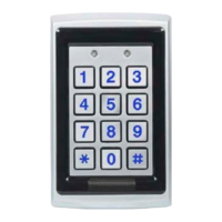
1. 确定合适的读卡器安装位置。
2. 撕下装置中包含的自粘式安装标签模板的背部,
放在要安装的位置。
3. 按照模板上的指南钻两个孔(安装模板上说明了
孔的大小和位置),以便将读卡器安装在表面。
4. 钻一个 1/2" (13 mm) 大小的孔,以便安装电缆。
如要安装在金属上,则在孔的边缘装一个索环或
者粘一圈电气胶带。
5. 将读卡器和/或电源的接口电缆接到主机。建议使
用线性电源。
Při montáži čtečky na povrch postupujte následovně:
1. Určete vhodnou montážní polohu pro čtečku.
2. Odloupněte zadní samolepicí montážní štítek
šablony včetně jednotky a umístěte do požadované
montážní polohy.
3. Šablonu použijte jako vodítko. Vyvrtejte dva otvory
(velikost otvoru a poloha je označena na montážní
šabloně) pro montáž čtečky na povrch.
4. Pro kabel vyvrtejte otvor o velikosti 1/2" (13 mm).
Pokud budete montáž provádět do kovu, umístěte
okolo okraje otvoru průchodku nebo elektrikářskou
pásku.
5. Veďte kabel s rozhraním od čtečky a/nebo zdroje
napájení k hostitelské jednotce. Doporučujeme
lineární typ zdroje napájení.
Montage des Lesers an einer Oberfläche:
1. Eine geeignete Montagestelle für den Leser
bestimmen.
2. Den Abdeckstreifen der selbstklebenden Montage-
Vorlage abziehen, die mit dem Leser mitgeliefert
wurde, und diese an der gewünschten
Montagestelle anbringen.
3. Mithilfe der Vorlage zwei Löcher (Lochgröße und
-position sind auf der Montage-Vorlage angegeben)
zur Montage des Lesers auf der Oberfläche bohren.
4. Ein Loch mit 1/2 Zoll (13 mm) Durchmesser für das
Kabel bohren. Bei der Montage an einer Metallwand
eine Tülle oder Isolierband um die Kante des Lochs
kleben.
5. Das Schnittstellenkabel vom Leser und/oder Netzteil
zum Host verlegen. Es wird ein lineares Netzteil
empfohlen.
Per montare il lettore su una superficie, seguire i seguenti
passi:
1. Individuare una posizione di montaggio adeguata
per il lettore.
2. Eliminare il rivestimento di protezione dal retro del
modello di montaggio autoadesivo in dotazione con
l’unità, e disporlo nella posizione prescelta per il
montaggio.
3. Utilizzando il modello come guida, praticare due fori
(la dimensione e la posizione sono indicati sul
modello di montaggio) per montare il lettore sulla
superficie.
4. Praticare un foro da 1/2" (13 mm) per il cavo. Se la
superficie di montaggio è metallica, applicare una
guarnizione o del nastro isolante attorno al bordo
del foro.
5. Stendere il cavo di interfaccia dal lettore e/o
dall’alimentatore all’host. Si consiglia un
alimentatore di tipo lineare.
Doe het volgende voor het opbouwen van de lezer:
1. Leg een geschikte opbouwpositie vast voor de lezer.
2. Pel de achterkant van het zelfklevende
opbouwsjabloon af, dat bij de eenheid zit en
positioneer de gewenste opbouwpositie.
3. Boor, aan de hand van het sjabloon, twee gaten
(grootte en positie zijn aangeduid op het
opbouwsjabloon) om de lezer aan het oppervlak te
bevestigen.
4. Boor een gat van 1/2" (13 mm) voor de kabel. Bij
bevestigen aan metaal, plaats een doorvoertule of
isolatietape rond de rand van het gat.
5. Geleid de interfacekabel van de lezer en/of
stroomvoorziening naar de host. Een linair type
stroomvoorziening is aanbevolen.
Wiring Instructions
1. Prepare the controller cable by cutting its jacket
back 3 cm (1-1/4") and strip the insulation from the
wires about 1.2 cm (1/2").
2. Splice the reader’s pigtail wires to the
corresponding controller wires (as indicated in table
below) and cover each joint with insulating tape.
Note: When using a separate power supply for the reader,
the reader, power supply, and host must have a
common ground.
Instrucciones de cableado
1. Para preparar el cable del controlador, corte 3 cm
de la parte posterior de la envoltura y quite el
aislante de los cables alrededor de 1,2 cm.
2. Una los cables flexibles de conexión del lector con
los cables correspondientes del controlador (como
se indica en la tabla a continuación) y cubra cada
unión con cinta aislante.

 Loading...