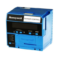
The Honeywell RM7800 is a microprocessor based inte-
grated burner control for automatically fired gas, oil, or
combination fuel single burner applications. The RM7800
consists of a Relay Module and Keyboard Display Module.
Subbase, Amplifier, and Purge Card are required to complete
the system. Options include Personal Computer Interface,
DATA CONTROLBUS MODULE™, Remote Display Mount-
ing, First-Out Expanded Annunciator and COMBUSTION
SYSTEM MANAGER™ Software.
The RM7800 is programmed to provide a level of safety,
functional capability and features beyond the capacity of
conventional controls.
Functions provided by the RM7800 include automatic
burner sequencing, flame supervision, system status indica-
tion, system or self-diagnostics and troubleshooting.
7800 SERIES
RM7800E,G,L,M Relay Module
—Expanded annunciator status.
—Total cycles of operation.
—Total hours of operation.
—Fault history of six most recent faults:
• Cycles of operation at time of fault.
• Expanded annunciator data at time of fault.
• Fault message and code.
• Hours of operation at time of fault.
• Sequence status at time of fault.
• Sequence time at time of fault.
—Diagnostic information:
• Device type.
• Flame amplifier type.
• Flame failure response time.
• Manufacturing code.
• On/Off status of all digital inputs and outputs.
• Selected prepurge time.
• Software revision and version of RM7800 and Key-
board Display Module.
• Status of configuration jumpers.
• Status of Run/Test Switch.
■ Safety features:
—Interlock check.
—Closed loop logic test.
—Dynamic AMPLI-CHECK™.
—Dynamic input check.
—Dynamic safety relay test.
—Dynamic self-check logic.
—Expanded safe-start check.
—High Fire Purge Switch test.
—Internal hardware status monitoring.
—Low Fire Start Switch test.
—Tamper resistant timing and logic.
■ Access for external electrical voltage checks.
■ Application flexibility.
■ Communication interface capability.
■ Dependable, long-term operation provided by microcom-
puter technology.
■ First-out annunciation and system diagnostics provided
by a 2 row by 20 column Vacuum Fluorescent Display
(VFD) located on the Keyboard Display Module.
■ First-out expanded annunciation with 26 Light Emitting
Diodes (LEDs) for limits and interlocks (optional).
■ Five sequence information Light Emitting Diodes (LEDs).
■ Five function Run/Test Switch.
■ Interchangeable plug-in flame amplifiers.
■ Local or remote annunciation of operation and fault
information.
■ Nonvolatile memory for retaining history files and se-
quencing status after loss of power.
■ Remote reset (optional).
■ Report generation (optional).
■ Burner controller data:
—Sequence status.
—Sequence time.
—Hold status.
—Lockout/alarm status.
—Flame signal strength.
S. H. • Rev. 9-92 • ©Honeywell Inc. 1992 • Form Number 65-0117—2
CONTENTS
Specifications............................................................ 2
Ordering Information ............................................... 2
Principle Technical Features ................................... 8
Safety Provisions ...................................................... 9
Installation.............................................................. 11
Wiring ..................................................................... 13
Assembly ................................................................. 20
Operation................................................................ 23
Static Checkout ....................................................... 32
Checkout ................................................................. 35
Troubleshooting...................................................... 42


 Loading...