7800 SERIES RELAY MODULES
32-00213—01 8
Mounting RM7838A Relay Module
1. Mount the RM7838A on the 7800 Subbase verti-
cally, or mount horizontally with the knife blade ter-
minals pointing down. When mounted on the
Q7800A, the RM7838A must be in an electrical
enclosure.
2. When mounted in an electrical enclosure, provide
adequate clearance for servicing, installation and
removal of the RM7838A, keyboard display module,
flame amplifier, signal probes, electrical signal volt-
age probes and electrical connections.
a. Allow an additional two inches (51 mm) below
the RM7838A for the flame amplifier mounting.
b. Allow an optional three-inch (76 mm) minimum
to both sides of the RM7838A for electrical sig-
nal voltage probes.
3. Make sure no subbase wiring is projecting beyond
the terminal blocks. Tuck in wiring against the back
of the subbase so it does not interfere with the knife
blade terminals or bifurcated contacts.
IMPORTANT
The RM7838A must be installed with a plug-in
motion rather than a hinge action.
4. Mount the RM7838A by aligning the four L-shaped
corner guides and knife blade terminals with the
bifurcated contacts on the wiring subbase and
securely tightening the two screws without deform-
ing the plastic.
5 4-9 - Automatic main fuel
valve(s) opens.
1. Listen for and observe operation of the main fuel valve(s)
and actuator(s).
2. Valve(s) and actuator(s).
6 4-3 - Alarm (if used) turns
on.
1. Alarm.
7 May need
to jumper
limits
and/or
Running
Interlocks
19-L2 Manually drive damper
motor open and look
for High Fire Switch
closure.
1. High Fire Switch.
2. Firing rate motor and transformer.
3. Burner control.
4. Limits.
5. Running Interlocks.
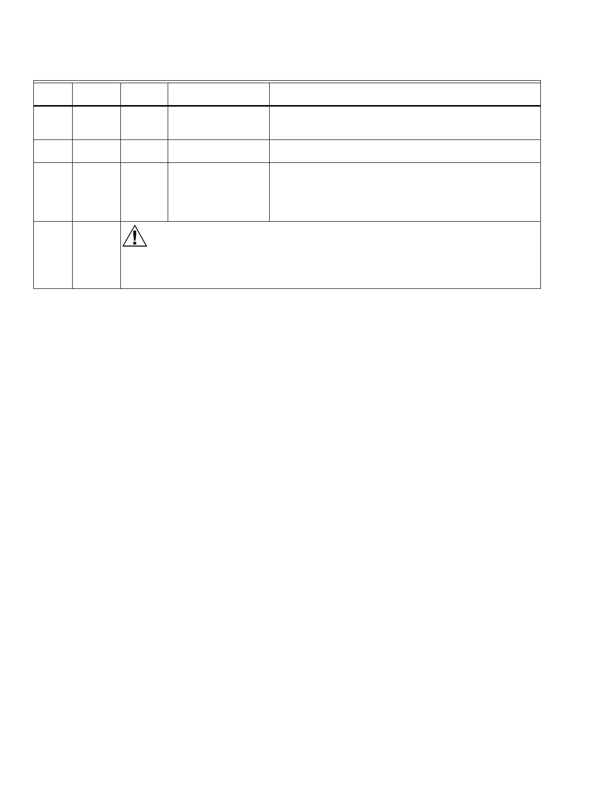
FINAL ALL
Equipment Damage Hazard.
Can cause equipment damage.
After completing these tests, open the master switch and remove all test jumpers from the
subbase terminals. Also remove bypass jumpers from limits if used.
Table 6. Static Checkout
Test
No.
Test
Jumpers
Voltmete
r Normal Operation
If Operation is Abnormal,
Check the Items Listed Below
 Loading...