S89E,F DIRECT SPARK IGNITION CONTROL MODULE
68-0066—4 6
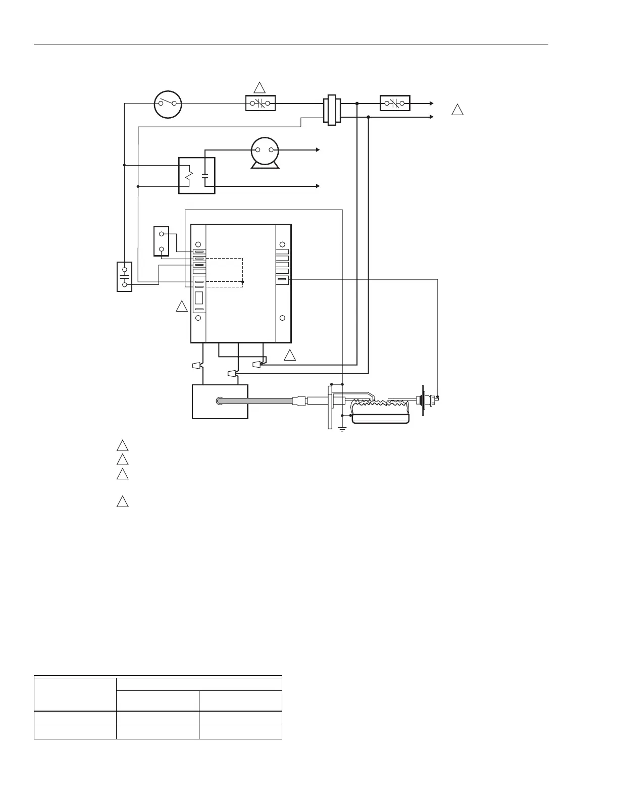
Fig. 3. S89F typical hookup in direct spark control system. See Fig. 9 for control system ladder diagram.
10. Turn off gas supply.
11. Gas control closes.
12. The module begins the safe start check (S89E: 10
seconds maximum) or safe start check plus valve on
delay (38 seconds maximum) after which the igniter
starts and gas control opens.
13. Time system until gas control closes. S89 is now in
safety lockout. The lockout time should be within the
specifications in Table 2.
14. Open gas supply. System remains off and no gas flows
to the main burner.
Table 2. S89 Lockout Times.
Resetting S89 After Safety Lockout
Once the S89 locks out, it must be reset before the system will
operate. To reset, set the thermostat below room temperature,
wait at least 45 seconds, then turn the thermostat up to call for
heat. The system should start normally. If adjusting the
thermostat does not reset the S89, turn off power to the
appliance for 45 seconds and then turn it on.
Final Checkout
With power and gas supply on, set thermostat to call for heat
and observe operation through at least one complete cycle to
make certain that all controls are operating safely.
OPERATION
The S89 is powered by a 24V transformer. It operates in
response to a call for heat from the thermostat.
BLUE
WHITE
GROUND
BURNER
IGNITER
M19837
FLAME
SENSOR
120 V SPARK
GENERATOR
BLACK
AIR
PROVING
SWITCH
DUAL VALVE
COMBINATION
GAS CONTROL
COMBINATION
AIR BLOWER
RELAY
THERMOSTAT OR
CONTROLLER
COMBUSTION AIR
BLOWER MOTOR
GND (BURNER)
24V (GND)
24V
VALVE
S89F GAS PRIMARY
TRANSFORMER
L2
L1
(HOT)
L2
L1
(HOT)
LIMIT
CONTROLLER
VALVE (GND)
SENSE
BLUE
1
4
2
3
3
2
1
4
POWER SUPPLY. PROVIDE DISCONNECT MEANS AND OVERLOAD PROTECTION AS REQUIRED.
ALTERNATED LIMIT CONTROLLER LOCATION.
IMPORTANT:
• CONNECT L1 TO THE BLACK LEAD.
• CONNECT L2 TO THE WHITE LEAD. OTHERWISE THE S89 WILL NOT DETECT THE FLAME AND WILL LOCK OUT.
FACTORY TEST TERMINAL. DO NOT USE.
Lockout Time
Shown on S89
Module
Safety Lockout Time
Minimum Maximum
4 seconds 3.0 seconds 5.5 seconds
11 seconds 8.0 seconds 15.0 seconds
 Loading...


