1 69-0753J. H. • 11-92 • ©Honeywell Inc. 1992 • Form Number 69-0753
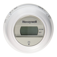
T874 Multistage
Thermostat and Q674 Subbase
Application
The T874D Thermostat and Q674E Subbase provide 24
to 30 Vac control of standard 2 stage heating and 2 stage
cooling systems.
The Y594D includes the TG504 Thermostat Guard,
field-adjustable range stops and field-adjustable locking
levers.
Operation
The stages of heat make sequentially as the temperature
drops. Make refers to the mercury switch initiating a call for
heat or cool.
There are about 2° F [1° C] between stages so that the
second stage makes only when the first stage cannot handle
the load. This is the interstage differential.
Installation
WHEN INSTALLING THIS PRODUCT…
1. Read these instructions carefully. Failure to follow
them could cause a hazardous condition.
2. Check the ratings given in the instructions and on
the product to make sure the product is suitable for your
application.
3. Installer must be a trained experienced service
technician.
4. After installation is complete, check out product
operation as provided in these instructions.
CAUTION
1. Disconnect power supply to prevent electrical
shock or equipment damage.
2. To prevent interference with the thermostat
linkage, keep wire length to a minimum and
run wires as close as possible to the subbase.
3. Do not overtighten thermostat captive mount-
ing screws, because damage to subbase threads
can result.
4. Do not short across coil terminals on relay. This
can burn out the thermostat heat anticipator.
IMPORTANT: An incorrectly leveled subbase will cause
the temperature control to deviate from setpoint. It is
not a calibration problem.
LOCATION
Install the thermostat about 5 ft [1.5 m] above the floor
in an area with good air circulation at average temperature.
Do not install thermostat where it may be affected by:
— drafts, or dead spots behind doors and in corners.
— hot or cold air from ducts.
— radiant heat from sun or appliances.
— concealed pipes and chimneys.
— unheated (uncooled) areas behind the thermostat,
such as an outside wall.
MOUNT SUBBASE
The thermostat subbase can be mounted on a vertical
outlet box, horizontal outlet box or directly on the wall.
1. If you must mount the subbase on a vertical outlet
box, order Honeywell part no. 193121A Adapter Assem-
bly. See Fig. 1. The assembly includes an adapter ring, two
screws and a cover plate to conceal any holes or blemishes
on the wall. Install the ring and cover plate on the vertical
outlet box.
Fig. 1—Installation of Q674 Subbase on outlet
box.
M925
VERTICAL
OUTLET
BOX
ADAPTER
RING
SUBBASE
COVER
PLATE
MOUNTING
SCREWS (2)
MOUNTING
SCREWS (2)
1
SUBBASE
MOUNTING
SCREWS (2)
HORIZONTAL
OUTLET
BOX
1
2
2
1 NOT INCLUDED WITH UNIT.
2 ACCESSORY PARTS AVAILABLE (193121A).
For a wall installation, hold subbase in position and
mark holes for anchors. See Fig. 2. Wall anchors must be
obtained from local hardware store. Be careful that the
wires do not fall back into the wall opening. Set aside
subbase. Drill four 3/16 in. [4.6 mm] holes and gently tap
anchors into the holes until flush with the wall.
SUPER TRADELINE