VC SERIES
These two position 3 way hydronic valves are intended for use in a
normal indoor environment to control the flow of hot and/or cold water,
or glycol solution to 50% concentration.
They consist of an actuator, valve and replaceable valve cartridge
assembly. These valves can be piped for either diverting or mixing
valve applications in central heating and/or cooling systems; or for
individual fan coil, radiator or convector applications.
Depending on the model selected they can be controlled by either a
low or line voltage SPST OR SPDT controller such as a room
thermostat, aquastat or flow switch.
SPECIFICATIONS
The specifiatons follwing are nominal and conform to generally
accepted industry standards. Honeywell is not responsible for
damages resulting from misapplications or misuse of its products.
Voltage: Colour coded label
24V 50Hz; 24V 60Hz Models Blue
100-130V 50-60Hz Model Black
200-240V 50-60Hz Model Red
Power consumption :
6 Watts Max. at nominal Voltages(during valve position change)
Use 24 V Class 2 transformer. Provide 6 VA for transformer and
connection wire sizing.
Maximum duty cycle: 15 %
End switch rating :
2.2 A inductive from 5 to 110 Vac,
1.0 A inductive above 110 to 277 Vac.
Min. DC switching capability: 5 mA @ 24 Vdc
Nominal timing :
Valve opens in 6 seconds @ 60Hz (20% longer @ 50 Hz)
Electrical termination : Available in 2 versions,
(1) Molex™ (header # 39-30-1060). Requires mating connector
(receptacle/housing # 39-01-2060). OR
(2) With integral 1 meter [nominal 39"] leadwire cable.
Operating ambient temperature : 0 to 65°C [32 to 150°F]
Shipping & storage temperature:
-40 to +65 °C [-40 to +150°F]
Atmosphere: non-corrosive, non-explosive
Min. & max. fluid temperatures: 1° to 95°C [34°to 203°F].
(Short duration peak: 120°C [248°F])
Operating pressure differential : Max. - 4 Bar [60 psi ]
Pressure rating : Static - 20 Bar [300 psi]
Burst - 100 Bar [1500 psi]
Valve material: Body of bronze; cartridge of Ryton™ (polyphenylene
sulphide) & Noryl™ (polyphenylene oxide); O-ring seals of EPDM
rubber; stainless steel stem.
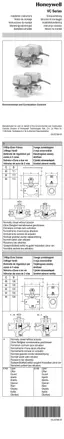
Dimensions / pipe fitting sizes / flow ratings (nominal Cv):
See Diagram.
3 - Way, Balanced Hydronic Valves
Nominal dimensions in mm and inches
* Includes compression nuts and olives
Dimensions
C
D Cv (nominal)
Pipe Fitting Sizes
mm
Inches mm Inches 6000 6100
3/8" FLARE (no adapter)
98
3 -7/8 136 5-11/32 3.0 2.7
1/2" SWEAT
98
3 -7/8 136 5-11/32 4.2 3.8
1/2" FLARE (no adapter)
98
3 -7/8 136 5-11/32 4.0 3.8
1/2" INVERTED FLARE (no adapter)
98
3 -7/8 136 5-11/32 4.2 4.2
1/2" BSPP (int.), 15 MM Comp.
98
3 -7/8 136 5-11/32 4.0 3.7
1/2" BSPT (int.)
98
3 -7/8 136 5-11/32 4.0 3.8
1/2" NPT (int.)
98
3 -7/8 136 5-11/32 4.0 3.7
3/4" BSPP (int.)
94
3-11/16 130 5-3/32 8.2 6.9
3/4" BSPT (int.)
94
3-11/16 130 5-3/32 8.2 6.2
3/4" BSPP (ext.)
94
3-11/16 130 5-3/32 8.0 6.7
3/4" NPT (int.)
94
3-11/16 130 5-3/32 8.6 6.6
3/4" SWEAT
94
3-11/16 132 5-3/16 7.5 5.9
22 MM* Compression
112
4-7/16 140 5-1/2 8.3 6.9
1" BSPP (int.)
94
3-11/16 136 5-11/32 9.0 7.5
1" BSPP (ext.),
94
3-11/16 136 5-11/32 9.0 7.9
1"BSPT(int.)
94
3-11/16 136 5-11/32 9.0 8.1
1" NPT (int.)
94
3-11/16 136 5-11/32 9.0 8.6
1" SWEAT
94
3-11/16 136 5-11/32 9.0 6.6
28 MM* Compression 116 4-9/16 147 5-13/16 9.0 7.5
2003.03.04 © Honeywell Limited.
Form No. 95C-10647-4