EasyManua.ls Logo

Honeywell VR8305 User Manual

Honeywell VR8305
12 pages
To Next Page IconTo Next Page
Page #1 background imageLoading...
Page #1 background image
G.G. • Rev. 10-91 • © Honeywell Inc. 1991 • Form Number 69-0626—2
Application
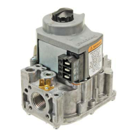
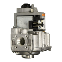
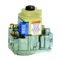
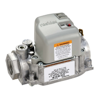
These direct ignition combination gas controls are used
in gas-fired appliances with capacities up to 300 feet
3
/hour
at 1 inch wc pressure drop [8.5 meters
3
/hour at 0.25 kPa]
on natural gas. They include a manual valve, two automatic
operators, and a pressure regulator. See Table 1 for tem-
perature ranges and regulator types.
VR8305 set up for natural gas includes a 393691 LP
Conversion Kit. The kit contains a cap screw, a pressure
regulator adjustment screw, a tapered spring and a conver-
sion label.
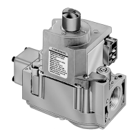
VR8305
Direct Ignition
Combination Gas Control
BODY PATTERN: Straight-through body pattern.
INLET X OUTLET SIZES AVAILABLE: 1/2 x 1/2 inch,
1/2 x 3/4 inch, and 3/4 x 3/4 inch (factory-installed inlet
flange).
ADAPTERS: Adapters available for 1/2 and 3/4 inch
straight and angle connections. Refer to Table 2.
ELECTRICAL RATINGS:
VOLTAGE AND FREQUENCY: 24 Vac, 60 Hz.
THERMOSTAT HEAT ANTICIPATOR SETTING:
0.7A.
CURRENT DRAW: 0.70A.
CAPACITY:
Size Capacity (at 1 inch Minimum Maximum
(Inlet x Outlet) wc pressure drop
a
)
Regulated Capacity Regulated Capacity
1/2 x 1/2 240 feet
3
/hour 30 feet
3
/hour 340 feet
3
/hour
[6.8 meter
3
/hour] [0.8 meter
3
/hour] [9.6 meter
3
/hour]
1/2 x 3/4 270 feet
3
/hour 30 feet
3
/hour 370 feet
3
/hour
[7.6 meter
3
/hour] [0.8 meter
3
/hour] [10.5 meter
3
/hour]
3/4 x 3/4 300 feet
3
/hour 30 feet
3
/hour 415 feet
3
/hour
[8.5 meter
3
/hour] 0.8 meter
3
/hour] [11.8 meter
3
/hour]
a
Capacity based on 1000 Btu/feet
3
, 0.64 specific gravity natural gas at 1 inch wc pressure drop [37.3 MJ/meter
3
, 0.64
specific gravity natural gas at 0.25 kPa pressure drop].
Honeywell
Use conversion factors in Table 3 to convert capacities for
other gasses.
TABLE 1—TEMPERATURE RANGES AND
REGULATOR TYPES.
Ambient
Model Temperature Regulator
Number Range Type
VR8305H 0° F to 175° F Slow-opening
[-18° C to +79° C]
VR8305K -40° F to 175° F Slow-opening
[-40° C to +79° C]
VR8305M -40° F to 175° F Standard-opening
[-40° C to +79° C]
VR8305P -40° F to 175° F Step-opening
[-40° C to +79° C]
APPROVALS:
American Gas Association design certificate:
UP-70-69A.
Canadian Gas Association design certificate:
UP-70-69A.
Australian Gas Association design certificate:
Applied for.
Delta C: P-70-42A19
TABLE 2—FLANGE PART NUMBERS.
Part Number
Inlet/ Without With
Outlet Flange Hex Hex
Pipe Size Type Wrench Wrench
1/2 inch NPT Straight 393690-6 393690-16
Elbow 393690-3 393690-13
3/4 inch NPT Straight 393690-4 393690-14
Elbow 393690-5 393690-15
NOTE: Flange Kits include one flange with attached O-
ring and four mounting screws.
TABLE 3—GAS CAPACITY
CONVERSION FACTORS.
Specific Multiply Listed
Gas Gravity Capacity By
Manufactured 0.60 0.516
Mixed 0.70 0.765
Propane 1.53 1.62

Other manuals for Honeywell VR8305

Question and Answer IconNeed help?

Do you have a question about the Honeywell VR8305 and is the answer not in the manual?

Honeywell VR8305 Specifications

General IconGeneral
BrandHoneywell
ModelVR8305
CategoryControl Unit
LanguageEnglish

Summary

Application Overview

Gas Control Capacity

Details product capacity based on inlet/outlet size and pressure drop for natural gas.

Product Specifications

Covers body pattern, available inlet/outlet sizes, and electrical ratings for the gas control.

Installation Instructions

General Safety and Installation Warnings

Covers critical safety warnings and cautions for installing the gas control.

Converting Between Gas Types

Detailed instructions for converting the gas control between natural and LP gas.

Adapters, Location, and Piping

Steps for installing adapters, choosing a location, and installing piping for the gas control.

Mounting and Connecting the Control

Procedures for mounting the gas control, connecting gas piping, and using wrenches.

Wiring the Gas Control

Wiring Diagrams

Illustrates wiring connections for S87 Direct Ignition and S89C Direct Ignition systems.

Wiring Precautions

Important notes on power supply, wiring compliance, and heat anticipator adjustment.

Start-Up and Checkout Procedures

Gas Leak Testing

Instructions for performing a gas leak test on pipe connections and the gas control.

Checking Gas Input

Procedures for checking and adjusting gas input to the main burner using a meter or manometer.

Pressure Regulator Adjustment

Guidance on adjusting the pressure regulator to match appliance specifications.

Safety Shutdown Performance

Steps to test the safety shutdown mechanism of the gas control system.

Maintenance and Service

Preventive Maintenance

Importance of regular maintenance, factors affecting frequency, and when to replace the control.

Troubleshooting Common Issues

Guidance on diagnosing and resolving issues like the main burner not coming on.

Homeowner Operating Instructions

Safety Warnings for Homeowners

Critical safety warnings for homeowners regarding gas appliance operation.

Appliance Operation and Shutdown

Instructions for operating the appliance and performing vacation or complete shutdown.
Related product manuals