XIO FAMILY OF SPECTRUM SYSTEM REMOTE INPUT/OUTPUT DEVICES
5 31-00360—01
Din Rail Un-Mounting
1. Remove all wiring connectors from the device to
expose DIN latch release
2. Pull down DIN latch release with one hand to release
the fastener from the DIN rail.
3. Lift the bottom of the controller away from the DIN
rail with your other hand.
4. Unhook the top ridge of the DIN rail channel on the
back of the controller from the top of the DIN rail.
NOTE: Use caution when pulling the DIN latch release!
Over extending the DIN latch release can damage
the resistance spring of the mechanism.
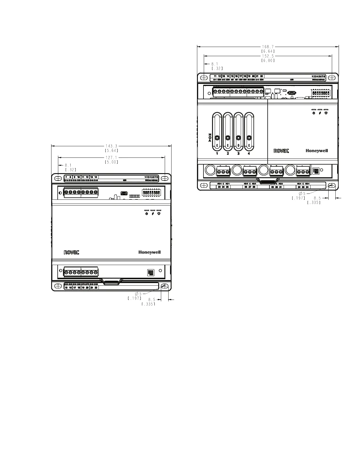
Panel Mounting
Fig. 6. xio.RIM, xio-RIMCT, xio.AOM, xio.CIM, xio.8IM
Modules Mounting Hole Dimensions.
Fig. 7. xio.ROM, xio.CCM, xio.COM Modules Mounting
Hole Dimensions.
1. Position the base of the product level against the
panel wall and mark the wall to show the location of
the corner holes.
2. The XIO I/O device mounts using four screws
inserted through the corners of the base. Fasten
securely with four No. 6 or No. 8 machine or sheet
metal screws.
WIRING
A removable terminal block is used to make all wiring
connections to the XIO device. Attach all wiring to the
appropriate terminal blocks. All wiring must comply with
applicable electrical codes and ordinances, or as specified
in installation wiring diagrams (see “Wiring Method” on
page 7).
Users have the option to connect devices via daisy chain
(using the supplied removable terminal block) or connect
devices via the bus connectors (on the right (female) and
left (male) side of the device). RS-485 cabling must run
inside metal conduits to prevent unauthorized tapping
and/or injection of data into the communication lines.
NOTES:
— Bussed installation of XIO Remote I/O is lim-
ited to a maximum of five (5) modules
— Users can also connect to the XIO power and
communication bus (edge) connectors, not to
exceed a maximum of five (5) modules on 1
bus. Be sure to use a transformer which is ade-
quately rated to supply power to all bus con-
nected modules.
 Loading...


