Copyright © 2008 Honeywell GmbH All Rights Reserved EN1B-0410GE51 R0908A
XL 800 Series
FOR SMOKE CONTROL
HONEYWELL EXCEL 5000 OPEN SYSTEM
INSTALLATION AND COMMISSIONING INSTRUCTIONS
CONTENTS
General ............................................................................... 3
Before Installation ............................................................. 3
Installation ......................................................................... 3
Wiring ................................................................................. 4
XL800 Series Power Consumption ................................ 5
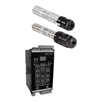
I/O Modules ................................................................... 5
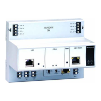
Description of the XCL8010AU Controller Module ......... 7
Overview........................................................................ 7
Interfaces and Bus Connections .................................. 10
Technical Data............................................................. 10
System Data........................................................... 10
Operational Environment ....................................... 10
Smoke Control Configuration....................................... 10
Data File Set-Up .......................................................... 11
Panel Reset ................................................................. 11
Typical Power Limited Circuit for XL800 ...................... 11
Connecting Single Bus Controller Systems ................. 11
XCL8010AU, I/O Modules on Single Rail............... 12
Multiple Rails in Single Cabinet.............................. 12
LonWorks Bus I/O Modules in Separate Rooms .... 12
How to Connect Panel Bus and LONWORKS Bus Mixed
Controller Systems ...................................................... 12
Connecting I/O Modules......................................... 12
Connecting I/O Modules to the XCL8010AU.......... 12
Setting Address of Panel Bus I/O Modules .................. 13
Setting the I/O Bus Switch ........................................... 14
LONWORKS Bus Topologies.......................................... 14
C-Bus Topologies ........................................................ 14
Mounting/Dismounting Modules.................................... 14
Mounting/Dismounting Controller/Sockets ................... 15
Mounting Sockets................................................... 15
Connecting Sockets ............................................... 15
Dismounting Sockets ............................................. 16
Mounting/Dismounting Electronic Modules .................. 16
Mounting Electronic Modules ................................. 16
Dismounting Electronic Modules ............................ 17
Connecting via C-Bus .................................................. 17
Connecting to the Controller................................... 17
Setting the C-Bus Termination Switch.................... 17
Shielding ................................................................ 17
Connecting HMIs or Laptops........................................ 17
Connecting the XI582 Operator Interface ............... 17
Connecting Laptops (XL-Online/CARE) ................. 18
XCL8010AU Terminals........................................... 18
Features....................................................................... 18
LONWORKS Interface and Terminals ....................... 18
LONWORKS Service LED and Button....................... 18
C-Bus Tx LED and Rx LED .................................... 19
Reset Button........................................................... 19
HMI Interface.......................................................... 19
Alarm and Power LEDs .......................................... 20
Watchdog Status .................................................... 20
Modem Interface..................................................... 20
I/O Bus Switch S2................................................... 20
C-Bus Termination Switch S1................................. 21
Memory .................................................................. 21
Description of the I/O Modules ....................................... 21
Common Features ....................................................... 21
Analog Input Modules .................................................. 22
Types of Analog Input Modules .............................. 22
Features ................................................................. 22
Terminals................................................................ 22
XFL821AU Connection Examples .......................... 23
Analog Output Modules................................................ 24
Types of Analog Output Modules ........................... 24
Features ................................................................. 24
Terminals................................................................ 24
Technical Data........................................................ 24
Modules with Manual Overrides ............................. 25
XFL822AU Connection Example ............................ 25
Synchronization Behavior of Analog Output Module
Configured as Floating Output................................ 25
Binary Input Modules ................................................... 26
Types of Binary Input Modules ............................... 26
Features ................................................................. 26
Terminals................................................................ 26
Technical Data........................................................ 26
Status LEDs............................................................ 27
XF823AU Connection Examples ............................ 27
Relay Output Modules.................................................. 28
Types of Relay Output Modules ............................. 28
Features ................................................................. 28
Terminals................................................................ 28
Permissible Loads .................................................. 29
Status LEDs with Manual Overrides ....................... 29
Connection Examples............................................. 30