PAGE 3 OF 7 0114 IH-3956
PARTS
ASSEMBLY CONTINUED
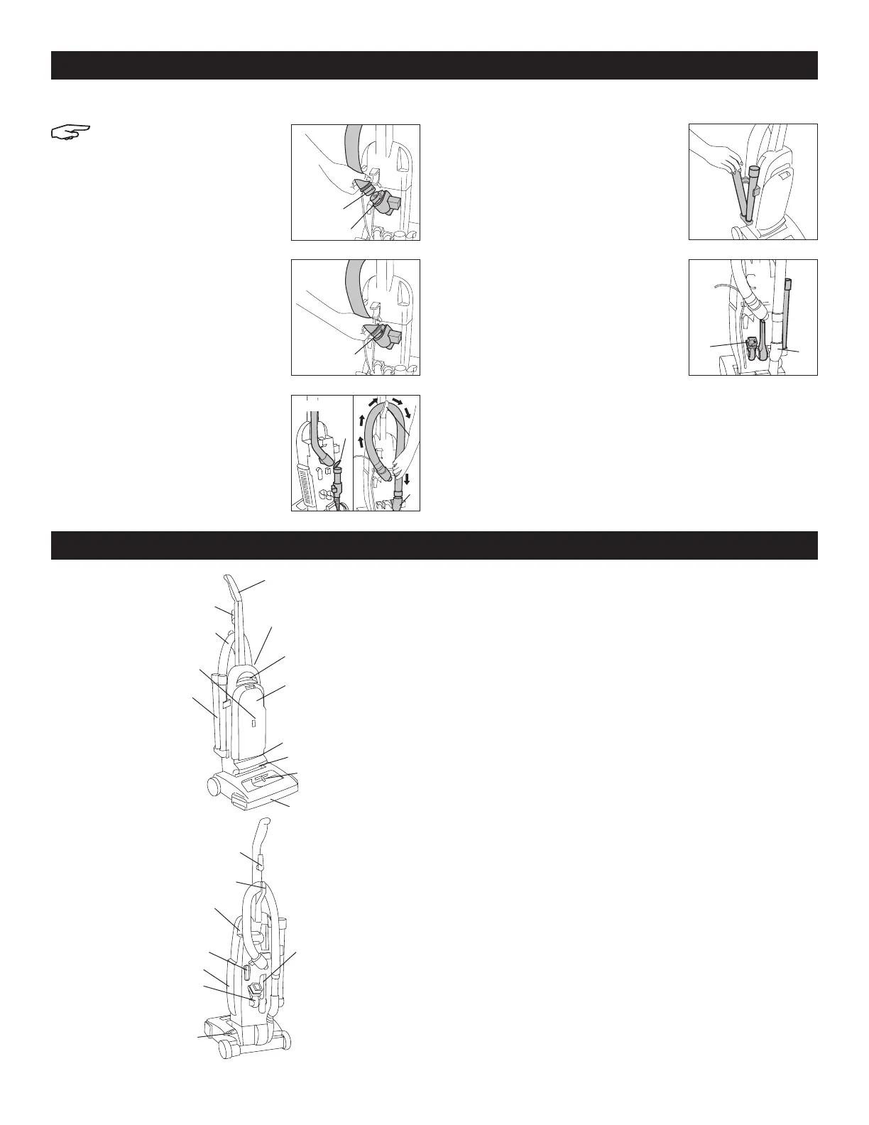
ATTACH HOSE
NOTE: Hose must be
connected as shown for all
operations.
1. Align end of hose with
projections (A) over slots (B) in
dirt duct. (See Figure 6)
2. Slide hose into dirt duct and
twist hose to lock projection into
slot (B). (See Figure 7)
3. Lift hose tube cover (C).
Position hose over hose hook
(D) and onto hose tube (E).
(See Figure 8)
POSITION TOOLS
4. Place smaller, smooth end of
wand into bottom of rack. Snap
wand into clip. Repeat with
other wand. (See Figure 9)
5. Snap ends of dusting brush/
furniture nozzle (F) and crevice
tool (G) into clips as shown.
(See Figure 10)
Figure 6
Figure 9
Figure 10Figure 7
Figure 8
A
B
B
C
D
E
F
G
1. Handle
2. Cord hooks: wrap cord around hooks for storage.
The top hook can be rotated right or left for easy
cord release.
3. Hose
4. ON/OFF switch: located on left rear corner of
vacuum body
5. Carrying handle
6. Bag door
7. Stair cleaning handle: located on lower edge of
bag door
8. Handle release lever: step on lever to lower handle
to operating or low positions
9. Headlight
10. Nozzle control knob: slide knob to correct setting for
height of carpet being cleaned
11. Furniture guard: helps prevent vacuum from marking
furniture
12. Wands
13. Check bag indicator
14. Final filter exhaust
15. Dusting brush/furniture nozzle
16. Crevice tool
17. Hose hook
2
8
14
15
4
17
2
16
2
3
4
5
6
7
10
11
12
13
9
 Loading...