3
2
Fig.2
Fig.5
Fig.6
Fig.11
Fig.12
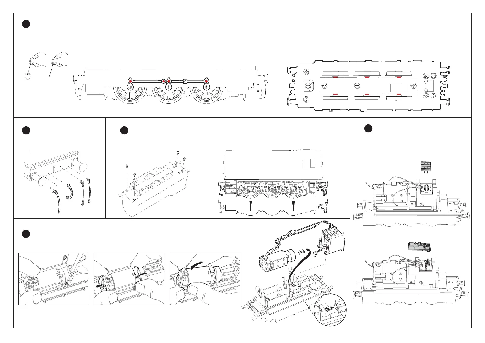
Apply one drop of oil to each of the connecting rod pivots indicated in red (Fig.2) on both sides
Fig.3
Apply one drop of oil to each of the axle bearings indicated in red (Fig.3).
To remove the Motor
Remove screws as shown in Fig.7. Remove motor by easing out of the retainer as shown in Figs.8 and 9.
4
Fig.7
Fig.8
Fig.10
Fig.9
Lubrication
1
Accessories
2
Fig.1
Fig.4
IMPORTANT – Only apply small single drops of light machine oil to the places indicated in red in Figs 2 and 3. This is best achieved by making a simple oil ‘dropper’ as illustrated in Fig.1. Insert a straightened paper clip into a cork and use a
bottle cap as a container for the oil. A small drop of oil can then be picked up by the dropper and applied in exactly the right place. Immediately wipe off any excess oil, especially from the locomotive body. Only lubricate moving parts.
To remove the Locomotive Body
Remove the four assembly screws from the underside of the locomotive (Fig.5).
Holding the locomotive the right way up, gently ease the chassis downwards from the body (Fig.6).
3
DCC Ready
Location of DCC Ready socket (Fig.11)
and Sound/DCC Decoder (Fig.12)
5
 Loading...