16
3) Lift the P200 or P201 connector from the PCB.
4) Place the new component on the PCB. Be sure that it matches the PCB footprint.
5) Solder the new component.
DP connector P300
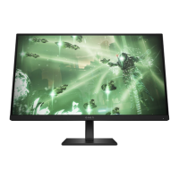
Repair the DP connector:
1) Use a soldering iron and a de-soldering pump to remove as much solder as possible from the pin.
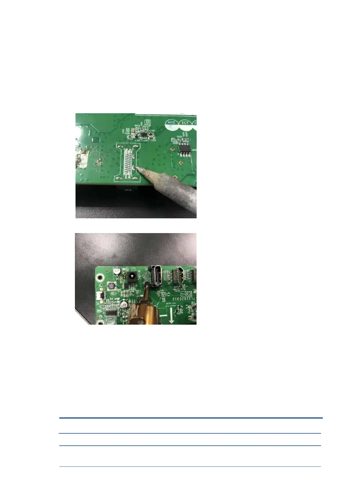
2) Use a hot air gun to melt the solder on the pins.
3) Lift the P300 connector from the PCB.
4) Place the new component on the PCB. Be sure that it matches the PCB footprint.
5) Solder the new component.
Function test
After repair, be sure to confirm that all functions are working.
Te
st item
Operating description Tool used
HDMI test Confirm whether image displays and sound plays
correctly on the monitor.
Computer or DVD player
DP test Confirm whether image displays and sound plays
Computer or DVD player
Test item Operating description Tool used
 Loading...