When replacing the system board, be sure that the following components are removed from the defective
system board and installed on the replacement system board:
●
Memory modules (see
Memory module on page 42)
●
RTC battery (see
RTC battery on page 44)
●
WLAN module (see
WLAN module on page 45)
●
Fan/heat sink assembly (see
Fan/heat sink assembly on page 71)
●
Processor (see
Processor on page 73)
Remove the system board:
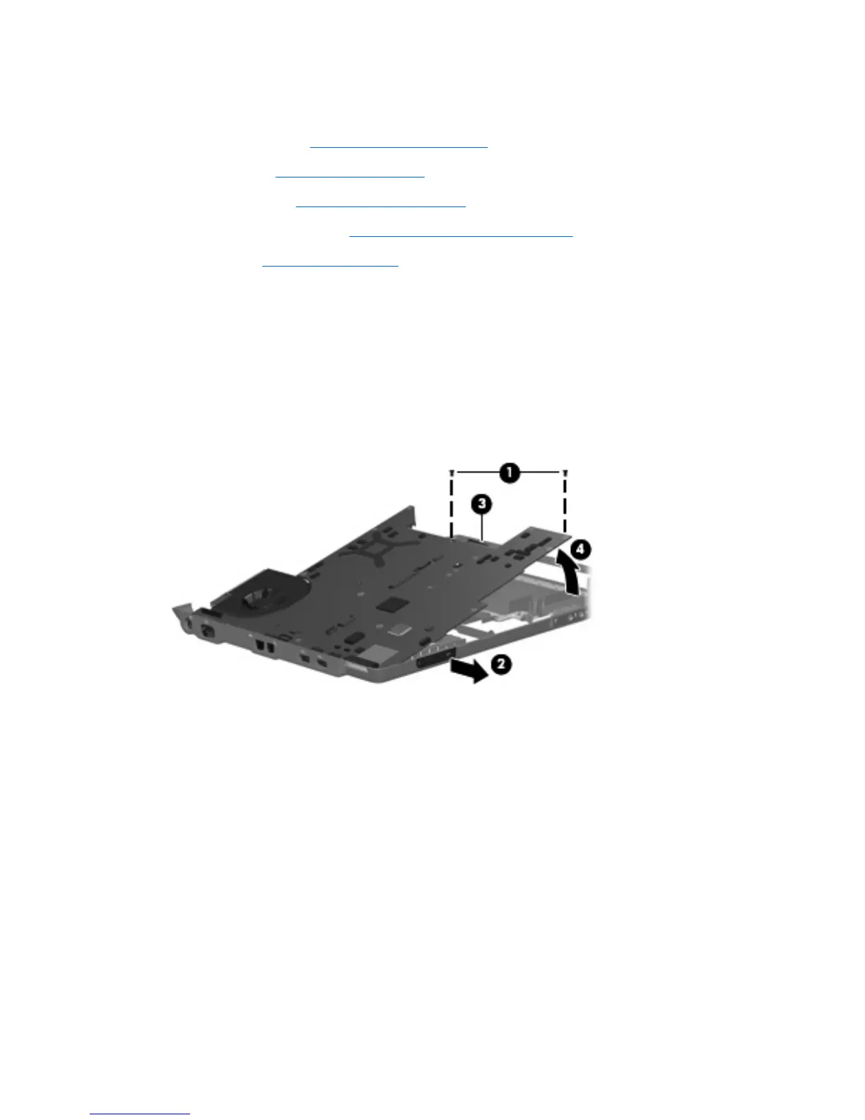
1. Remove the two Phillips PM2.5×5.0 screws (1) that secure the system board to the base enclosure.
2. Flex the front edge of the base enclosure (2) forward until the audio connectors clear the openings
in the base enclosure.
3. Use the optical drive connector (3) to lift the right side of the system board (4) until it rests at an
angle.
4. Disconnect the audio board cable (1) from the system board.
5. Disconnect the USB board cable and power connector cable (2) from the system board.
66 Chapter 4 Removal and replacement procedures
 Loading...