Do you have a question about the HP L1710 and is the answer not in the manual?
| 3D | No |
|---|---|
| HD type | - |
| Panel type | TFT |
| Pixel pitch | 0.264 x 0.264 mm |
| Display surface | Matt |
| Display diagonal | 17 \ |
| Display resolution | 1280 x 1024 pixels |
| Display technology | LCD |
| Vertical scan range | 50 - 77 Hz |
| Horizontal scan range | 24 - 83 kHz |
| Contrast ratio (typical) | 800:1 |
| Viewing angle, horizontal | 160 ° |
| Display brightness (typical) | 300 cd/m² |
| Supported graphics resolutions | 1280 x 1024 (SXGA) |
| UNSPSC-code | 43211902 |
| On/off switch | Yes |
| Power requirements | 100 - 240 VAC, 50 - 60 Hz |
| Display viewable area (HxV) | 432 mm |
| HDMI ports quantity | 0 |
| Certification | ISO 13406-2 pixel defect guidelines, MPR-II, CISPR, VCCI, CSA(Canada), ACA (Australia), TUV and GS Mark (German ergonomic), BSMI (Taiwan), CCC (China), MIC (South Korea), NOM (Mexico), Eastern European approvals, CE Marking, FCC approval, TCO '03 (emissions, ergonomics, environment), Microsoft Windows certified (Microsoft Windows 2000, Microsoft Windows XP, and Windows Vista), UL listed, GOST (Russia), SASO (Saudi Arabia), Restrictions of Hazardous Substances (RoHS) Directive, 2002/95/EC, Waste Electrical and Electronic Equipment (WEEE) Directive, 2002/96/EC |
| Product color | Silver |
| Country of origin | China |
| Market positioning | Business |
| Tilt angle range | -5 - 25 ° |
| Cable lock slot type | Kensington |
| Panel mounting interface | 100 x 100 mm |
| AC input voltage | 100 - 240 V |
| AC input frequency | 50 - 60 Hz |
| Power consumption (standby) | 2 W |
| Power consumption (typical) | 30 W |
| Operating temperature (T-T) | 5 - 35 °C |
| Non-operating relative humidity (non-condensing) | 5 - 90 % |
| Package weight | 6100 g |
| Sustainability certificates | ENERGY STAR |
| Cables included | AC, VGA |
| Depth (with stand) | 192 mm |
|---|---|
| Width (with stand) | 377 mm |
| Height (with stand) | 386 mm |
| Weight (with stand) | 4700 g |
| Depth (without stand) | 57 mm |
| Height (without stand) | 316 mm |
| Weight (without stand) | 3920 g |
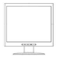
Visual representation of the monitor's main components and their interconnections.
Basic steps for setting up and powering on the monitor.
Description and function of each control button on the monitor's front panel.
Details on adjusting picture settings like brightness, contrast, and image control via OSD.
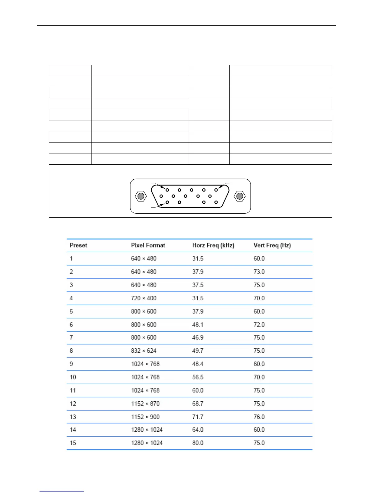
Pinout details for the D-SUB VGA connector.
List of supported resolutions, horizontal, and vertical frequencies.
General specifications and features of the LCD panel used in the monitor.
Detailed optical performance parameters of the LCD panel.
Diagram illustrating the monitor's software operation flow.
Schematic showing the electrical interconnections of the monitor's main components.
Detailed electrical schematic for the monitor's main logic board.
Electrical schematic of the monitor's power supply and inverter board.
Schematic diagram for the monitor's button control interface.
Physical layout of components on the main logic board.
Physical component layout for the power board.
Physical layout of components on the key board.
List of necessary tools and equipment for servicing the monitor.
Troubleshooting guide for common monitor issues.