Switch-connect configurations
For switch-connect configurations, connect cables from
the P2000 G3 MSA controller to the switch ports, and
from switch ports to data hosts.
Consider the following about figures in this section:
• These figures show simple, common cabling
configurations. Other cabling configurations exist.
• These figures show generic representations of
servers and switches.
• Simple, common cable configurations are included
in this document. For additional supported
cable/controller configurations, see the HP P2000
G3 MSA System Cable Configuration Guide,
available at http://www.hp.com/support/manuals.
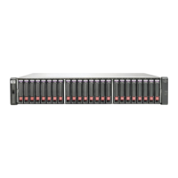
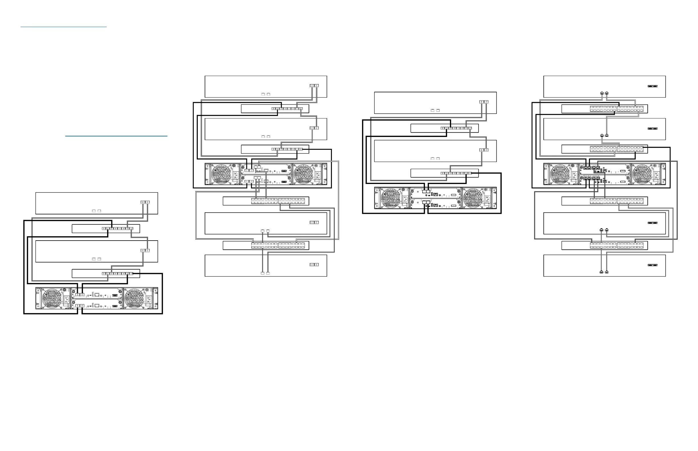
P2000 G3 FC MSA connected to two switches/two
servers
Connecting a P2000 G3 FC MSA dual-controller array
enclosure to two switches/two servers in a dual-path
configuration requires eight (8) Fibre Channel cables.
P2000 G3 Combo FC/iSCSI MSA connected to four
switches/four servers
Connecting a P2000 G3 Combo FC/iSCSI MSA
dual-controller array enclosure to four switches/four
servers in a dual-path configuration requires eight (8)
Fibre Channel cables and eight (8) Ethernet cables.
P2000 G3 10GbE iSCSI MSA System connected to two
switches/two servers
Connecting a P2000 G3 10GbE iSCSI MSA
dual-controller array enclosure to two switches/two
servers in a dual-path configuration requires four (4)
cables from the MSA to the switch (optical cables with
SFP+ transceivers or SFP+ 10GbE copper cables) and
four (4) Ethernet cables from the switch to the host.
P2000 G3 iSCSI MSA connected to four switches/four
servers
Connecting a P2000 G3 iSCSI MSA dual-controller
array enclosure to four switches/four servers in a
dual-path configuration requires sixteen (16) Ethernet
cables.
Page 5
 Loading...