19
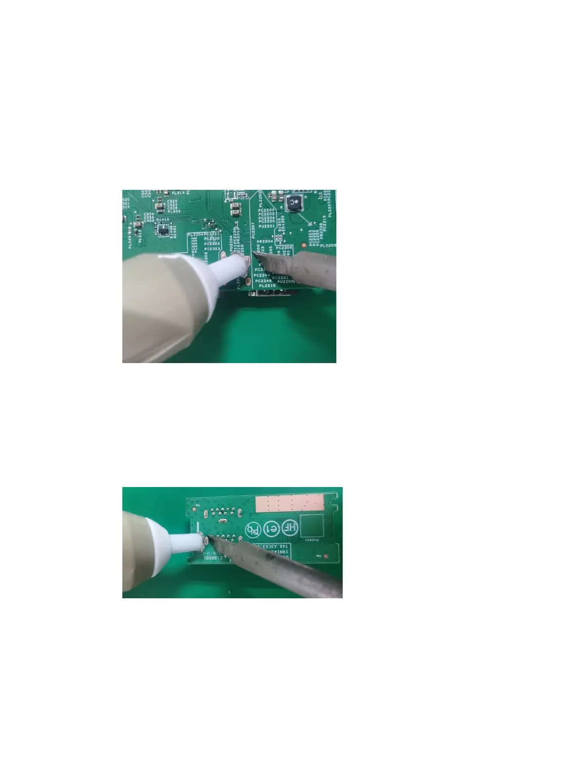
Solder the new component
USB-A connector USB2/USB3
Repair the USB-A connector:
1) Use a soldering iron and a de-soldering pump to remove as much solder as possible from the pin.
2) Lift the USB-A connector from the PCB.
3) Place the new component on the PCB. Be sure that it matches the PCB footprint.
4) Solder the new component.
USB-A connector USB4/USB5
Repair the USB-A connector:
1) Use a soldering iron and a de-soldering pump to remove as much solder as possible from the pin.
2) Lift the USB-A connector from the PCB.
3) Place the new component on the PCB. Be sure that it matches the PCB footprint.
4) Solder the new component.
Function test
After repair, be sure to confirm that all functions are working.
 Loading...