2-20
Installing the Switch
Installation Procedures
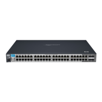
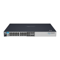
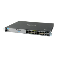
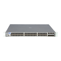
Installing the Switch
LEDs
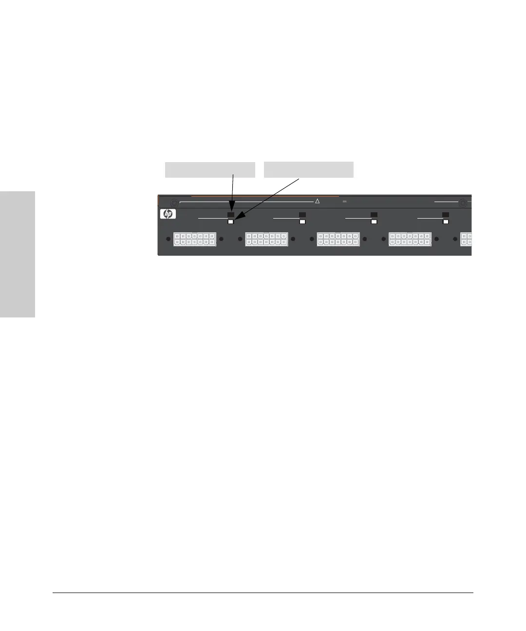
The RPS LEDs are located on the back of the EPS/RPS. These LEDs are
duplicated on the front of the device for your convience. The following graphic
shows an example of the back of the EPS/RPS. There are two green LEDs for
each RPS port:
■ Device Connected
■ Power Status
The following states provide status of an EPS/RPS port.
Fault Device
Connected
Power
Status
Message
Off Off Off Nothing Connected
On or Off Off On Not a valid state - should never happen
Off On Off Switch is connected, RPS is available but
not required
Off On On RPS is powering the connected device
Blinking Off Blinking RPS port is in fault mode
Off On Blinking Switch is requesting power, RPS can not
provide it
Blinking On Off Switch is unplugged, but RPS is powering
switch
Device Connected
Power Status
R1 R2 R3 R4
RPS 1 RPS 2 RPS 3 RPS 4
RPS Power: 12V backup to one connected device. Lowest-numbered port has priority.
!
Device Connected LED
Power Status LED
 Loading...