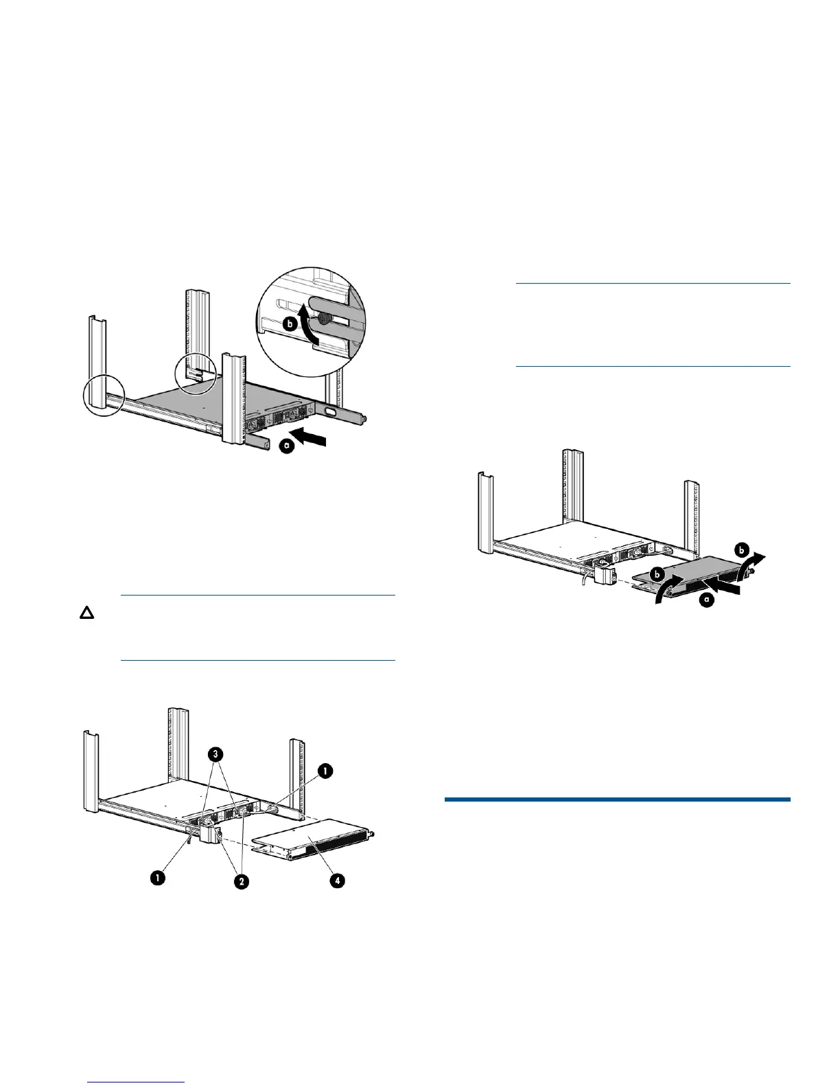
5. Install the switch. See Figure 5 (page 4).
a. From the front of the rack, slide the switch
(with inner rails attached) onto the outer rails,
taking care to align the inner rails with the
attachment screws on the outer rails at the
rear of the rack.
b. When the switch is in place, secure the inner
rails to the outer rails by tightening the screws
at the rear of the rack.
Figure 5 Installing the switch in the rack
6. At the front of the rack, run the switch power cords
from the sides of the rack through the cutouts in
the rail, and then connect them to the switch
power supplies. See Figure 6 (page 4).
CAUTION: Ensure that the power cords
do not come in contact with any sharp
edges.
Figure 6 Connecting power
3. Power switches1. Cutouts for power cords
4. Plenum2. Power cable plugs
7. Connect the other end of the power cords to
power sources on separate circuits to protect
against AC failure.
Ensure that the cords have a minimum service
loop of 6 inches available and are routed to
avoid stress.
8. Power on the power supplies by setting both
power switches to the ON position (I).
The power supply LEDs are amber until the Power
On Self Test (POST) is complete, and then change
to green. The HP SN6000B 16Gb FC Switch
takes several minutes to boot and complete POST.
NOTE: When installed, the plenum covers
the power supply switches and LEDs.
However, the LEDs are visible through the
air holes in the front of the plenum.
9. Attach the plenum. See Figure 7 (page 4).
Figure 7 Attaching the plenum
a. Slide the plenum over the nonport side of the
inner rails, taking care to bypass the power
cables.
b. Tighten the thumbscrews to secure the plenum
to the front of the rack.
10. Proceed to “Switch setup” (page 5).
Install a standalone switch
1. Unpack the switch and verify the contents as
described in “Verify the carton contents” (page
1).
Page 4
 Loading...