lp-65 Rev. 002 Rel. 010 Date 10.11.19
6
E. Temperature and Pressure Relief Valve
A factory installed temperature and pressure long element relief valve,
meeting the requirements for relief valves for water heaters (ANSI
Z21.22 / CSA 4.4) has been installed for your safety and convenience.
If servicing, make sure that the relief valve is sized to the BTU/hour
capacity and storage capacity of the water heater. If the relief valve
weeps see expansion tank section for details.
To avoid water damage or scalding due to relief valve operation:
• Discharge line must be connected to relief valve outlet and
run to a safe place of disposal. Terminate the discharge line
in a manner that will prevent possibility of severe burns or
property damage should the relief valve discharge.
• Discharge line must be as short as possible and the same
size as the valve discharge connection throughout its entire
length.
• Discharge line must pitch downward from the valve and
terminate at least 6” above the oor drain, making discharge
clearly visible.
• The discharge line shall terminate plain, not threaded, with a
material serviceable for temperatures of 375
o
F or greater.
• Do not pipe discharge to any location where freezing could
occur.
• No valve may be installed between the relief valve and heater
or in the discharge line. Do not plug or place any obstruction
in the discharge line.
• Test the operation of the relief valve after lling and
pressurizing the system by lifting the lever. Make sure the
valve discharges freely. If the valve fails to operate correctly,
immediately replace with a new properly rated relief valve.
• Test T&P valve at least once annually to ensure the waterway
is clear. If valve does not operate, turn the heater “o” and call
a plumber immediately.
• Take care whenever operating relief valve to avoid scalding
injury or property damage.
FAILURE TO COMPLY WITH THE ABOVE GUIDELINES COULD RESULT
IN FAILURE OF RELIEF VALVE OPERATION, RESULTING IN POSSIBILITY
OF SUBSTANTIAL PROPERTY DAMAGE, SEVERE PERSONAL INJURY,
OR DEATH.
Do not thread a cap or plug into the relief valve or relief valve line
under any circumstances! Explosion and property damage, serious
injury, or death may result.
RE-INSPECTION OF T&P RELIEF VALVES: T&P valves should be
inspected AT LEAST ONCE EVERY THREE YEARS, and replaced
if necessary, by a licensed plumbing contractor or qualied
service technician to ensure that the product has not been aected
by corrosive water conditions and to ensure that the valve and
discharged line have not been altered or tampered with illegally.
Certain naturally occuring conditions may corrode the valve and
its components over time, rendering the valve inoperative. Such
conditions can only be detected if the valve and its components are
physically removed and inspected. Do not attempt to conduct an
inspection on your own. Contact your plumbing contractor for a
re-inspection to assure continued safety.
FAILURE TO RE-INSPECT THE T&P VALVE AS DIRECTED COULD
RESULT IN UNSAFE TEMPERATURE AND/OR PRESSURE BUILD-UP
WHICH CAN RESULT IN PROPERTY DAMAGE, SERIOUS PERSONAL
INJURY, OR DEATH.
Use both thread tape and pipe dope to connect an NPT male X 3/4”
(minimum) pipe adapter. A shut-o valve between the hot water
supply and tank outlet is recommended for ease of service. Use a
back ow preventer designed for water heater installations. This valve
should be installed on the cold water ll supply line per local codes.
F. Scalding
An ASSE 1017 or ASSE 1070 temperature limiting or mixing valve
is recommended in installations servicing disabled or elderly
persons, or children. Mixing valves do not eliminate the risk of
scalding.
To avoid scalding:
• Set the water heater set point temperature as low as
possible.
• Feel water before bathing or showering.
• If thermostatic valves are required, use devices specically
designed for such purpose. Install these devices in
accordance with instructions provided by the manufacturer.
Failure to install a temperature limiting or mixing valve and
follow these instructions could result in property damage, severe
personal injury, or death due to scalds.
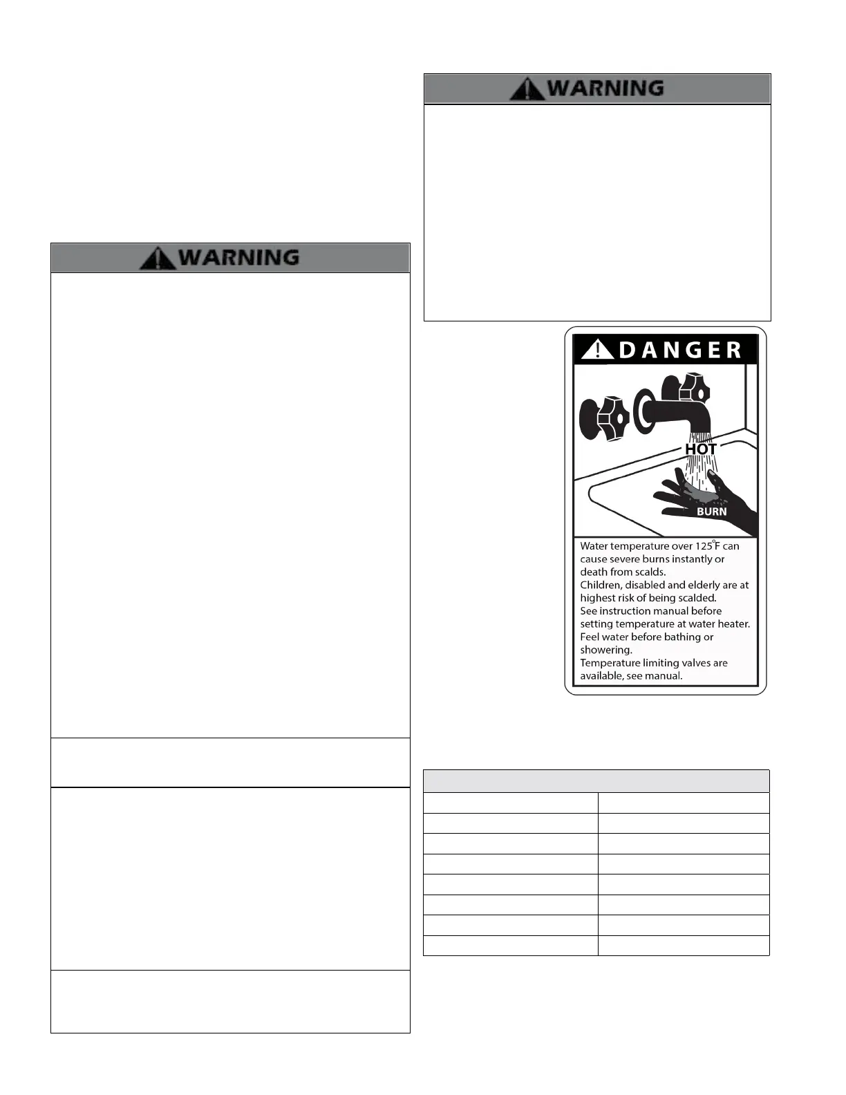
This water heater can
deliver scalding water. Be
careful whenever using
hot water to avoid scalding
injury. Certain appliances
such as dishwashers and
automatic clothes washers
may require increased
water temperatures. By
setting the thermostat
on this heater to obtain
the increased water
temperature required by
these appliances you may
create the potential for
scald injury.
To protect against injury,
install a mixing valve in the
water system. This valve
will reduce point of use
discharge temperatures
by mixing cold and hot
water in branch supply
lines. Such valves are
available from your local
plumbing supplier.
The following table details the relationship of water temperature
and time with regard to scald injury and may be used as a guide
in determining the safest water temperature for your applications.
Approximate Time / Temperature Relationships in Scalds
120
o
F More than 5 minutes
125
o
F 1 1/2 to 2 minutes
130
o
F About 30 seconds
135
o
F About 10 seconds
140
o
F Less than 5 seconds
145
o
F Less than 3 seconds
150
o
F About 1 1/2 seconds
155
o
F About 1 second
Table 3 - Approximate Time / Temperature Relationships in Scalds
 Loading...


