6
3
Installation Verification
5
Setting Monitoring Parameters
1. If no data collector is used, set the following parameters before connecting the SUN2000 to the
power grid. For the other parameter settings, see the SUN2000 (8KTL-28KTL) User Manual. If
a data collector is used, see the SmartLogger1000 User Manual for the parameter settings.
2. The preset password for Common User, Advanced User, and Special User is 000001. Use
the preset password to log in to the SUN2000 for the first time and then change the password
to a new one to ensure the account security.
4
System Power-on
1. Switch on the AC circuit breaker between the SUN2000 and the power grid.
2. Ensure that the DC Switch at the bottom of the SUN2000 is ON.
3. (Optional) Measure the temperatures at the joints between the DC terminals and the connectors.
1. Check that all screws, especially the screws used for electrical connections,
are secured.
2. Check that all circuit breakers are switched to OFF.
3. Check that the ground cable is securely connected and no short circuit
occurs.
4. Check that AC output power cables are connected correctly and securely
(the N wire is connected to hole 4, and L1/L2/L3 can be connected to any
hole of 1/2/3; for details, see 2.2 Install AC output power cables), with no
short circuit.
5. Check that DC input power cables are connected correctly and securely,
with no short circuit.
6. Ensure that idle DC input terminals are sealed.
7. Check that the idle USB and RS485 ports are plugged with waterproof
plugs.
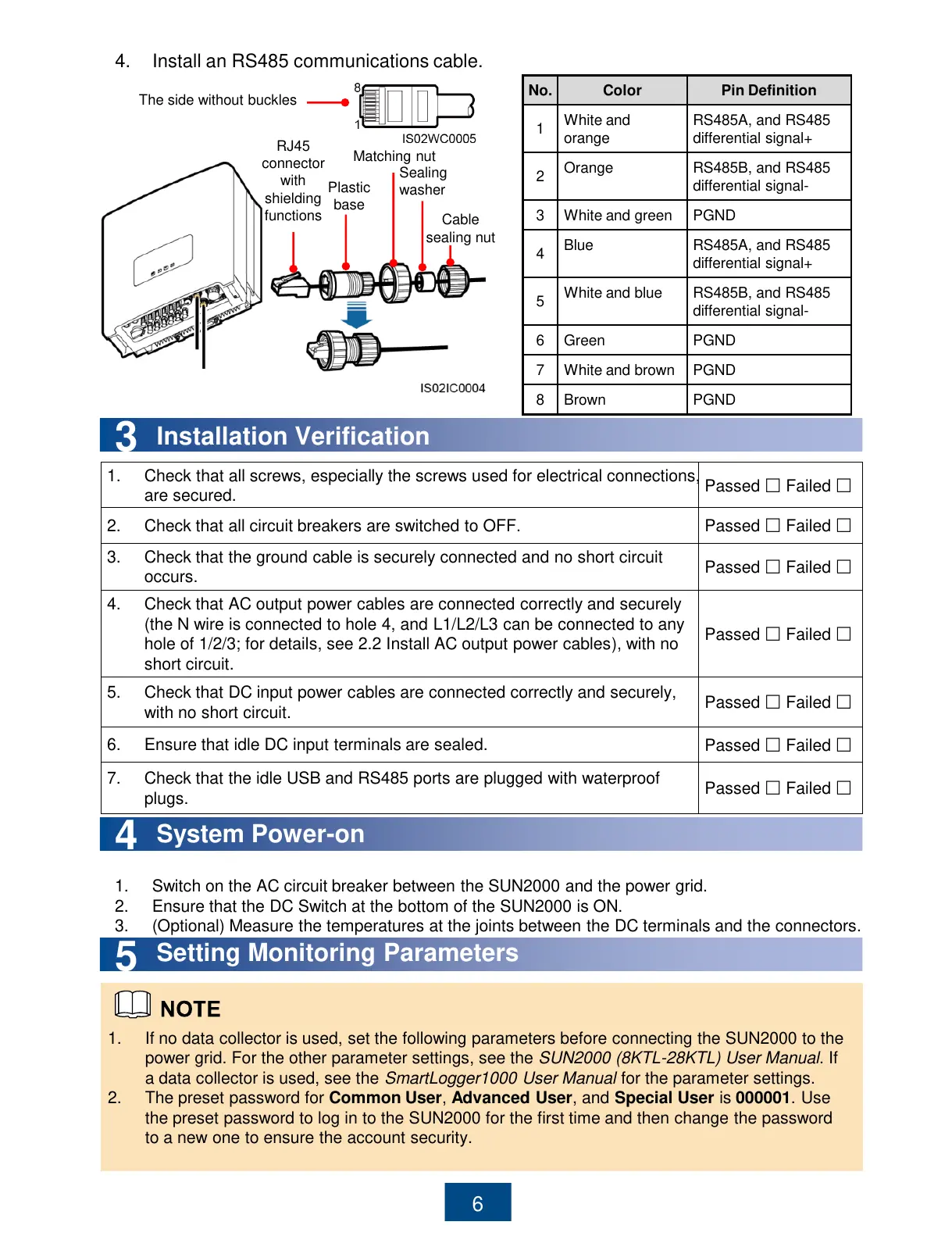
RS485A, and RS485
differential signal+
RS485B, and RS485
differential signal-
RS485A, and RS485
differential signal+
RS485B, and RS485
differential signal-
4. Install an RS485 communications cable.
RJ45
connector
with
shielding
functions
Plastic
base
Matching nut
Sealing
washer
Cable
sealing nut
The side without buckles
All manuals and user guides at all-guides.com
 Loading...