13
Pro-C Controller
INSTALLATION
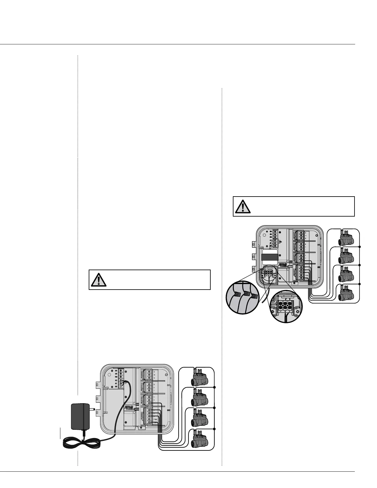
Connecting Valves and AC Power
1. Route valve wires between control valve
location and controller.
2. At valves, attach a common wire to either
solenoid wire of all valves. This is most
commonly a white colored wire. Attach a
separate control wire to the remaining
wire of each valve. All wire splice
connections should be done using water-
proof connectors.
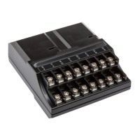
3. Open hinged faceplate on the controller to
access the terminal strip area.
4. Route valve wires through the conduit and
attach conduit to the controller at the large
conduit opening on the right side of the
bottom of the cabinet.
5. Strip ½" (13 mm) of insulation from ends
of all wires. Secure valve common wire to
C (Common) terminal on the first module.
Then attach all individual valve control
wires to appropriate station terminals.
Note: It is recommended that a licensed
electrician perform the following power
installation.
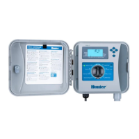
Indoor Cabinet
Route transformer cable through the left side
of the controller and connect the wires to
the screws marked AC. Before closing the
compartment door make sure wires hang in
the slotted areas so that the door can snap shut
without damaging wires.
Transformer
Valve 1
Va
lve 2
Valve 3
Valve 4
3 Wires AC2 Black
AC1 Black
GND Green
Connect the Two Black
Transformer Wires to
the Two AC Terminals
and the Green Wire to
the GND Terminal
alve Common Wire
alve
Wires
V
V
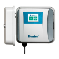
Outdoor Cabinet
Route AC power cable and conduit through
the ½" (13 mm) conduit opening on the left
side of the bottom of the cabinet. Connect
the wires to the transformer wires located
inside the junction box. International units
are supplied with a built in terminal strip.
Always use a UL listed conduit ½" (13 mm)
male adapter when installing the AC wiring.
Insert the adapter (male threads first) into the
½" hole at the bottom of the controller until it
enters the wiring enclosure. Attach the nut to
the adapter inside the enclosure.
NOTE: It is usually best to connect all field
wires prior to powering up the computer.
Valve Common Wire
Valve 1
Valve 2
Valve 3
Valve 4
Valve
Wires
230 or 250 VAC
110 VAC
 Loading...