6
ASSEMBLY
SHIFT
ROD
HAIRPIN
CLIP
SHIFT
LEVER
INDICATOR
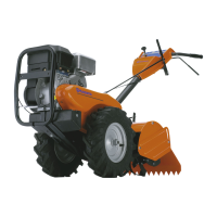
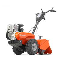
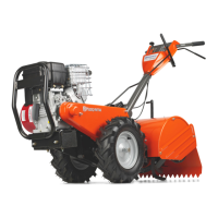
REMOVE TILLER FROM CRATE
• Make sure shift lever indicator is in “N” position (See
Fig. 7)
• Tilt tiller forward by lifting handle. Separate cardboard
cover from leveling shield.
• Rotate tiller handle to the right and pull tiller out of
carton.
CONNECT SHIFT ROD (See Fig. 7)
• Insert end of shift rod into hole of shift lever indicator.
• Insert hairpin clip through hole of shift rod to secure.
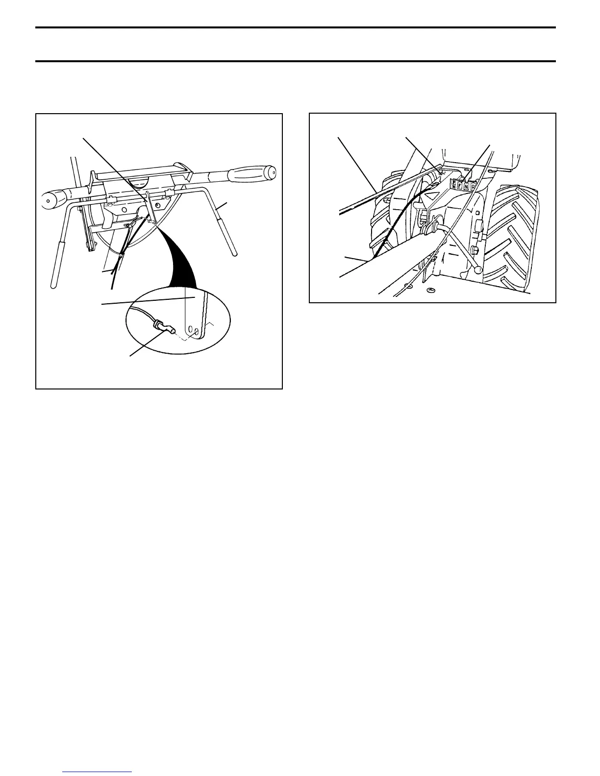
FIG. 7
FIG. 6
END OF CLUTCH
CABLE
CONTROL
BAR
CONTROL BAR
BRACKET
CONTROL BAR
BRACKET
CLUTCH
CABLE
ATTACH CLUTCH CABLE (See Fig. 6)
• Hook end of clutch cable through hole in control bar
bracket.
CHECK TIRE PRESSURE
The tires on your unit were overinfl ated at the factory for
shipping purposes. Correct and equal tire pressure is
important for best tilling performance.
• Reduce tire pressure to 20 PSI (1.4 kg/cm
2
).
HANDLE HEIGHT
• Handle height may be adjusted to better suit operator.
(See “TO ADJUST HANDLE HEIGHT” in the Service
and Adjustments section of this manual).
 Loading...