5
ASSEMBLY
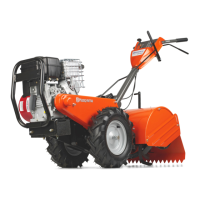
1. Remove the upper bolts on each side of the
drawbar and replace them with the shoulder bolts
supplied with the collection kit.
NOTE: It may necessary on some models, to
remove the rear tires to access the drawbar
shoulder bolts.
BAGGER SUPPORT ASSEMBLY
Draw Bar A
Original
Shoulder
Bolt
Support Assembly
Drawbar A
Kit
Shoulder
Bolt
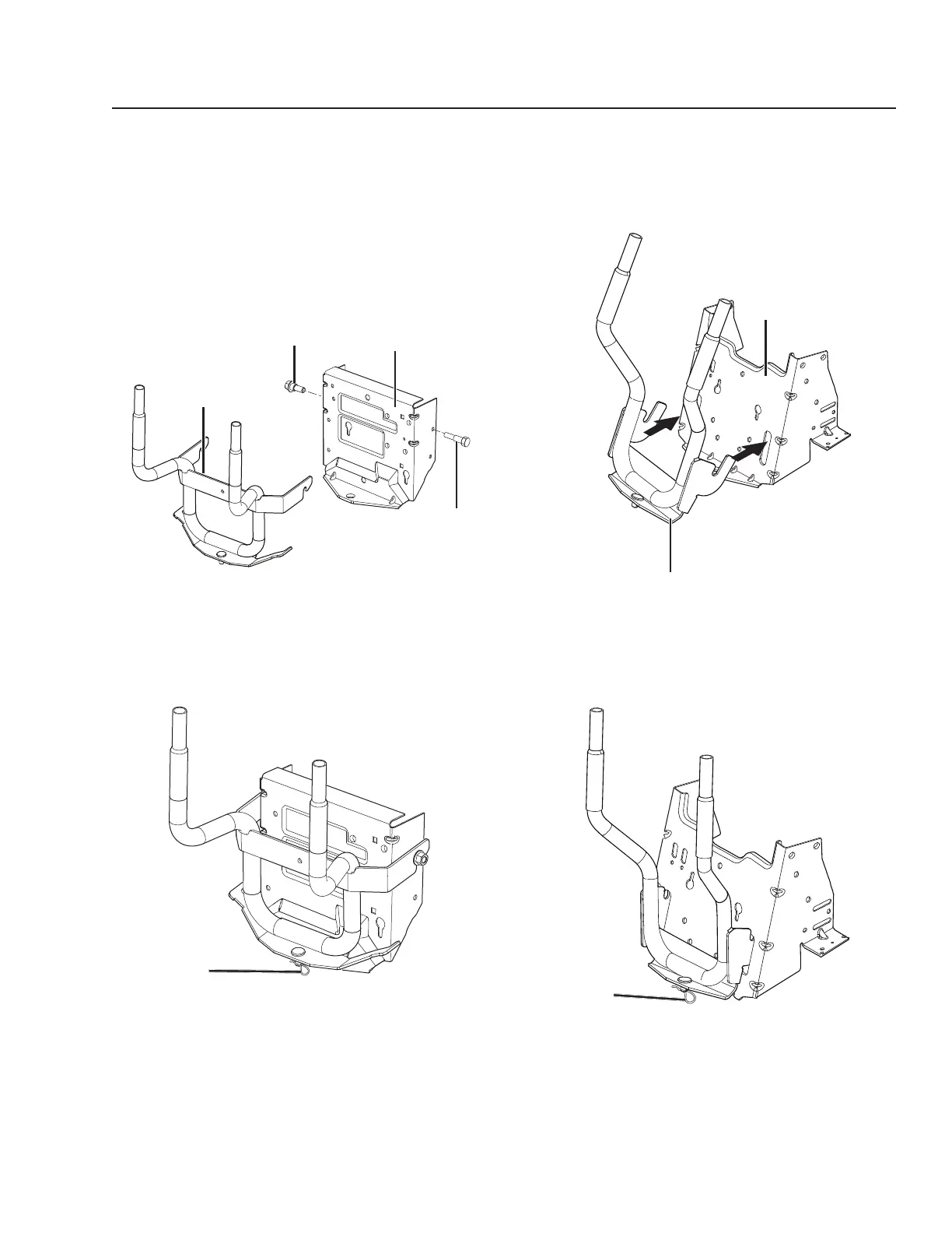
2. Hang the support assembly over the replacement
bolts and align the bottom pin into the drawbar.
Secure the bottom pin with a hairpin.
Draw Bar B
1. Slide the flanges of the support assembly in the
slots in the drawbar.
Hairpin
Drawbar B
Support Assembly
Hairpin
2. Pivot the assembly backwards to insert the bottom
pin into the drawbar. Secure the bottom pin with a
hairpin.
 Loading...