19
E
F
C
G
Q
R
D
K
G
P
B
L
M
A
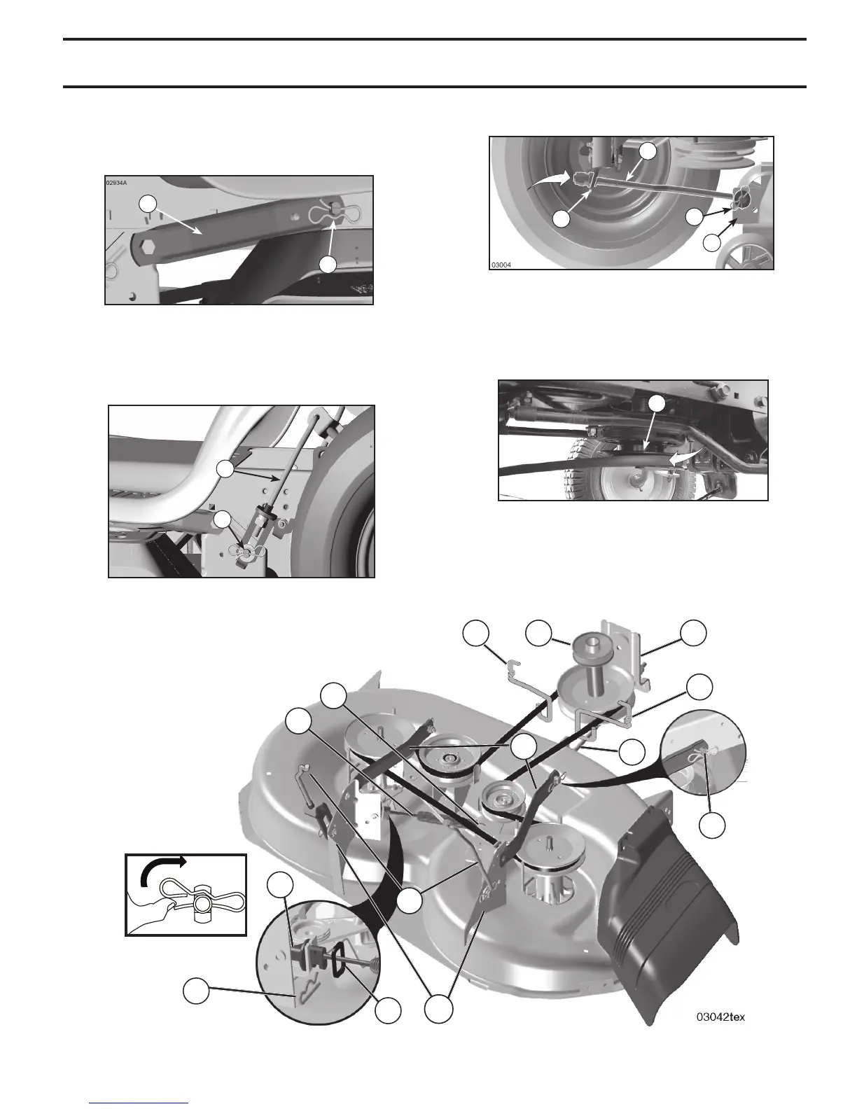
IMPORTANT: CHECK BELT FOR PROPER ROUTING
IN ALL MOWER PULLEY GROOVES.
• Raise attachment lift lever to highest position.
• If necessary, adjust gauge wheels before op er at ing
mower as shown in the Operation section of this manual.
E
F
H
J
M
Fig. 25
Fig. 26
A
B
D
C
Fig. 23
Fig. 24
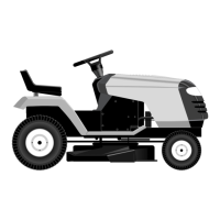
• ATTACH MOWER SIDE SUSPENSION ARMS (A) TO
CHASSIS - Position hole in arm over pin (B) on outside
of tractor chassis and secure with retainer spring.
• Repeat on opposite side of tractor.
• ATTACH REAR LIFT LINKS (C) - Lift rear corner of
mower and position slot in link assembly over pin (D)
on rear mower bracket and secure with washer and
retainer spring.
• Insert end of link (E) into hole in front mower bracket
and secure with washer and retainer spring (J).
• Hook end of clutch cable spring (Q) into hole in idler
arm (R).
• Push clutch cable housing guide (P) into bracket, slide
collar (L) onto guide and secure with retainer spring (K).
• Install belt on engine pulley (M), in belt keepers (G).
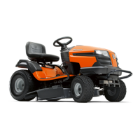
• ATTACH FRONT LINK (E) - Work from left side of trac-
tor. Insert rod end of link assembly through front hole
in tractor front suspension bracket (F).
Fig. 27
SERVICE AND ADJUSTMENTS
 Loading...