Page 6
Field Service Bulletin 801270
MAX200 UNDERWATER TORCH SUPPLEMENT
8376 7738 37
33
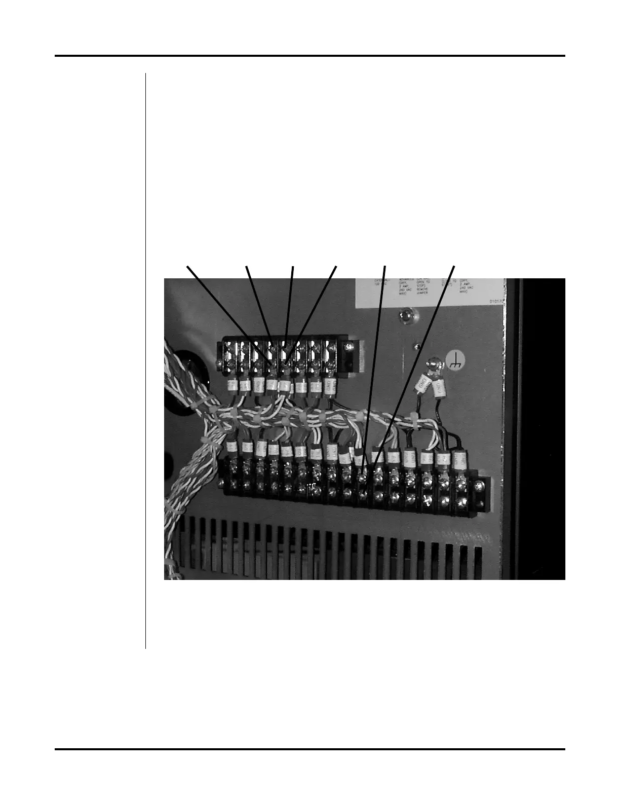
Figure 5 Remote Switch Connections to TB3 and TB4
7. At TB3, reconnect the remaining white lead pair marked 83 back to its original
terminal location. Also connect the remote switch red lead marked 33 to the 83
terminal location.
8. At TB4, connect the remote switch white lead marked 38 to the terminal that the
lead marked 76 (24 VAC Hot) is connected to. Also connect the remote switch
black lead marked 37 to the terminal that the power supply lead marked 77
(24 VAC Neutral) is connected to. See Figure 5.
 Loading...