Page 5
Field Service Bulletin 801270
MAX200 UNDERWATER TORCH SUPPLEMENT
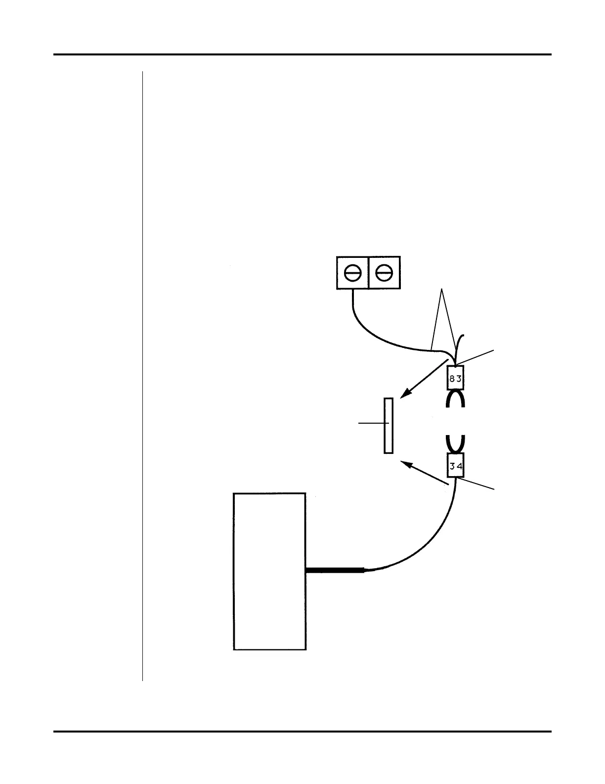
6. Splice the lead pair marked 83 that indicates continuity to TB2 with the remote
switch black lead marked 34 as follows (see Figure 4):
• Cut off the white lead pair above the 83 fork connector.
• Strip back the insulation on both leads 3/8" (10 mm), twist leads together
and crimp into one end of a butt splice.
• Cut off the remote switch black lead marked 34 above the fork connector.
• Strip back the insulation on the lead 3/8" (10 mm) and then crimp the
lead into the other end of the butt splice.
Cut here
Cut here
Butt splice
White lead pair
TB2
Remote
Switch
Figure 4 Splicing Remote Switch Wire 34 to Power Supply 83 Wires
 Loading...