EasyManuals Logo
Home>Hypertherm>Welding System>MAX200

Hypertherm MAX200 Field Service Bulletin

Hypertherm MAX200
10 pages
To Next Page IconTo Next Page
To Previous Page IconTo Previous Page
Page #7 background imageLoading...
Page #7 background image
Page 4
Field Service Bulletin 801270
MAX200 UNDERWATER TORCH SUPPLEMENT
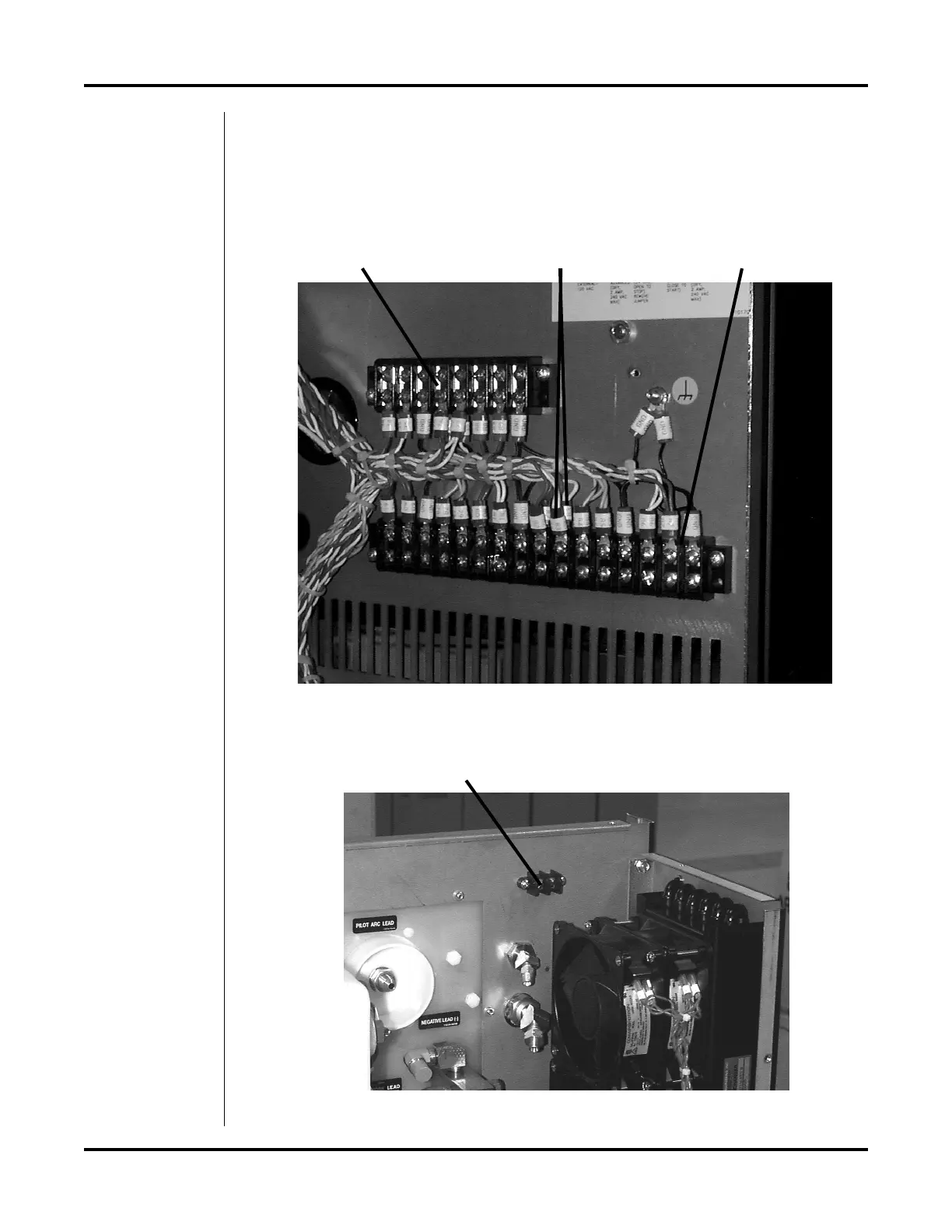
4. Locate terminal strips TB3 and TB4 on the inside, right side of the power supply.
5. At TB3, locate the 2 white lead pairs marked 83 and disconnect both wire pairs
from TB3. Determine which of the lead pairs connects with the torch start switch.
To do this, measure between each lead pair and the left terminal point on TB2 for
continuity. See Figures 2 and 3 below.
Figure 2 TB3 and TB4 Location
TB4 TB3
Figure 3 TB2 Location
Left terminal point of TB2
Wires marked 83

Other manuals for Hypertherm MAX200

Questions and Answers:

Question and Answer IconNeed help?

Do you have a question about the Hypertherm MAX200 and is the answer not in the manual?

Hypertherm MAX200 Specifications

General IconGeneral
BrandHypertherm
ModelMAX200
CategoryWelding System
LanguageEnglish

Related product manuals