MICROEDGE AND OMNICOM MOTHERBOARD REPLACEMENT
Field Service Bulletin 5
Omnicom installation
If you are replacing the motherboard in an Omnicom CNC and the DC power cable connector on the old motherboard
has 20 pins, use the following instructions to replace cables and DRAM module on the new motherboard. Refer to the
wiring diagram for details about cable routing and connectors.
1. Connect the DC power cable (CABL-0277) from this kit to the DC power connector on the motherboard.
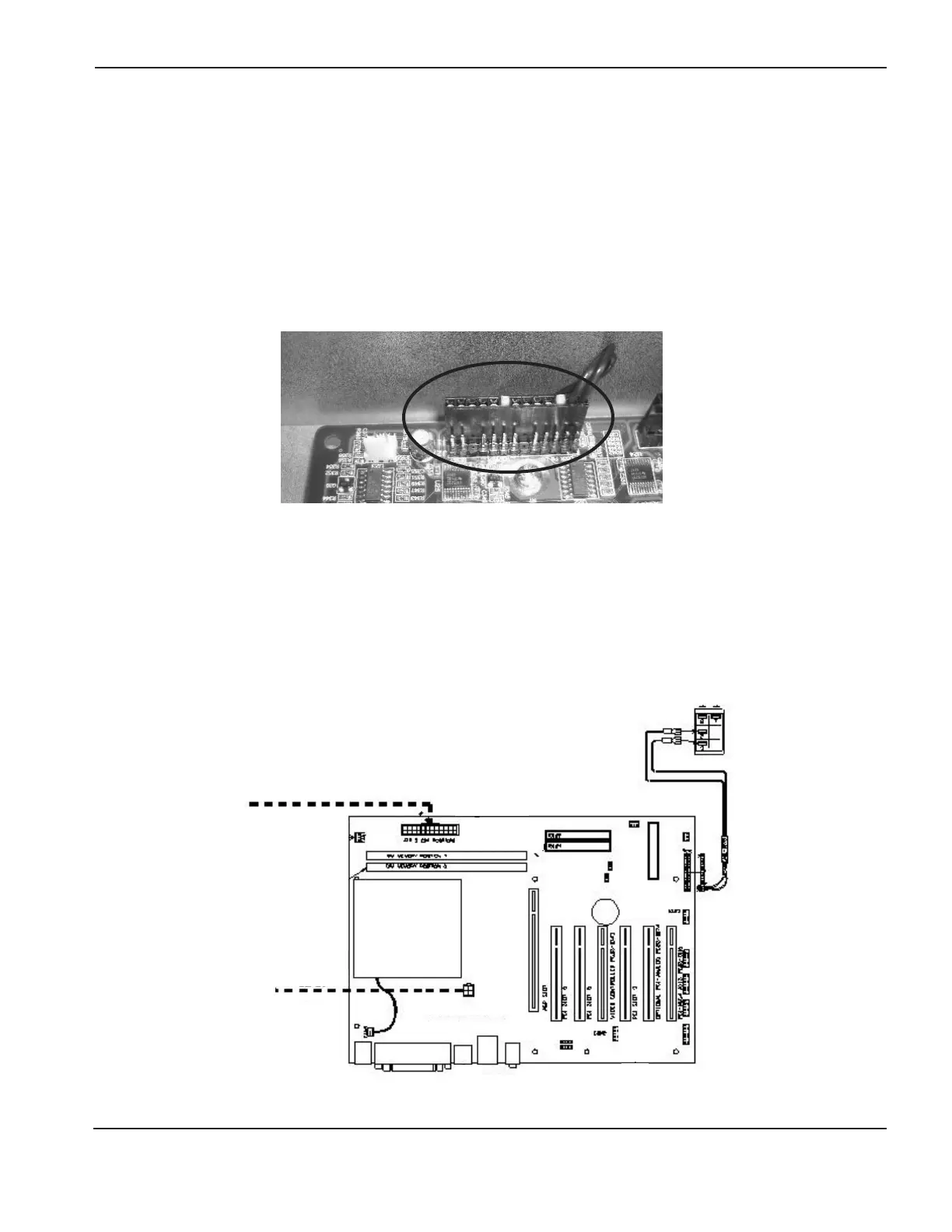
2. Connect the PS_ON cable (CABL-0279) from this kit to pins 12 and 13, next to the edge of the motherboard on
the PS_ON connector.
3. Connect the 12 V power cable and fan cables that you removed from the old motherboard to the appropriate
connectors on the new motherboard. Refer to the wiring diagram below.
4. Install the 512 MB DRAM module that you removed from the old motherboard.
12 V
Power
12 V Power cable
CABL-0279
CABL-0277
Fan cable
Omnicom motherboard wiring
Location and orientation of the PS_ON cable connector in an Omnicom installation
 Loading...

