3-4 powermax190c Service Manual
MAINTENANCE
Theory of Operation
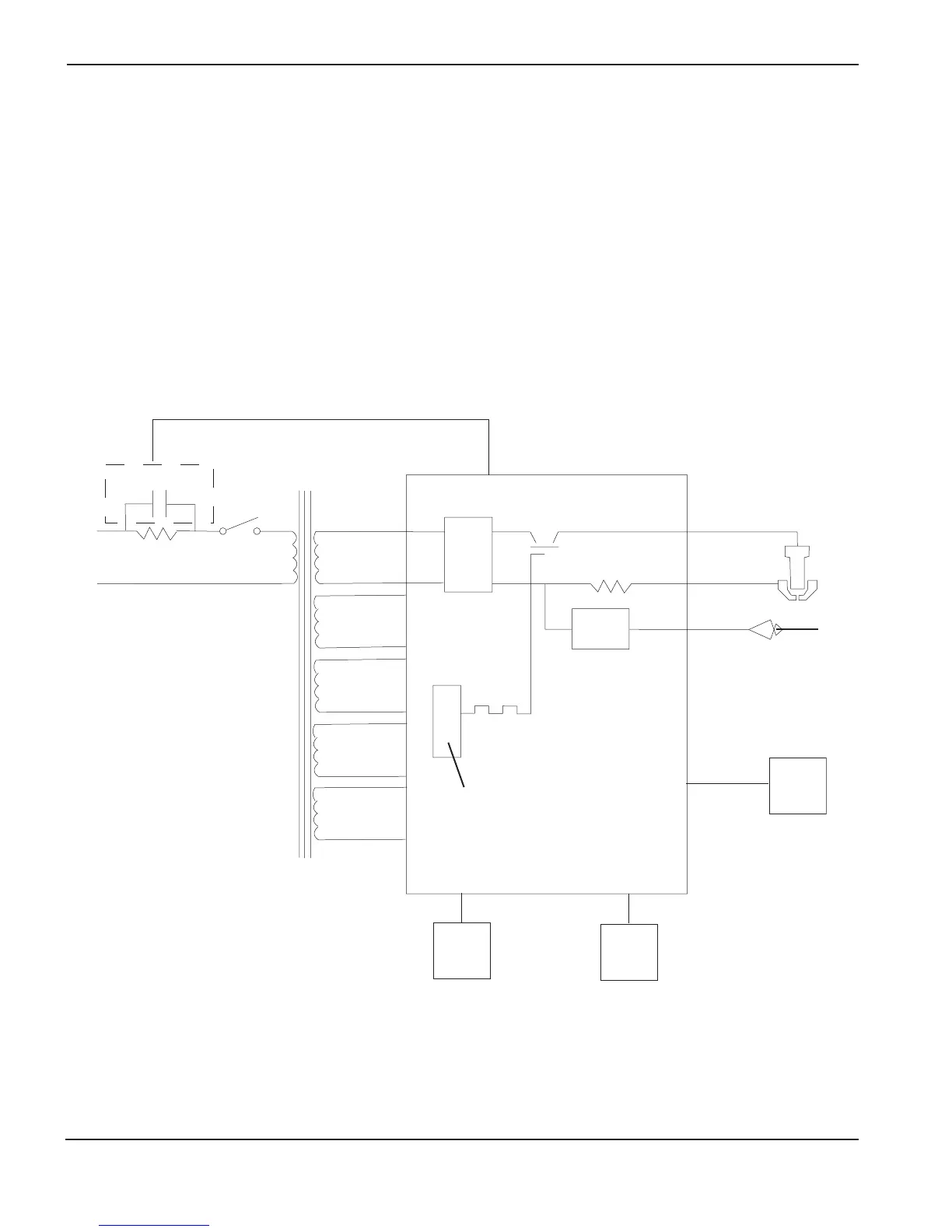
AC power enters the system through inrush resistor R1 into switch S1 then into the main transformer. The main
transformer T1 supplies voltage to the control circuitry and to the chopper module. The inrush contactor CR2 is
closed by the control circuitry on the power board PC1.
The chopper is incorporated into the power board PC1. The chopper consists of an isolated gate bipolar transistor
(IGBT). The IGBT is controlled by a pulse width modulated signal, set internally in the control circuitry on PC1.
The control circuitry regulates the output current, the air compressor, and the safety circuits. The output current is
set internally in the control circuitry to 12 amps. The air compressor operates during preflow, cutting, and post flow
modes. The compressor unit is set to output 40 psi (2.8 bar). The safety circuits consist of the cap sensor switch,
over voltage protection, and over temperature protection.
Work
Pilot Arc
Nozzle
Electrode
Cap
Sense
Over
Temp.
Air
Comp.
Current
Sense
Bridge
Pulse-width
modulator circuit
IGBT
T1
PC1
AC
in
S1R1
CR2
Powermax190c Block DIagram

 Loading...


