We recommend that you always use a primary/secondary piping
conguraon (see below for a basic conguraon).
In the case of hard water, use dislled or puried water. Glycol
systems require the use of propylene glycol. For large volume
systems, the opmum hardness is ≤2 grains.
Water Chemistry Allowable Limits
Acidity pH 6.6 - 8.5
Chloride < 125 mg/l
Iron < 0.5 mg/l
Copper <0.1 mg/l
Conducvity
<
400μS/cm (at 25°C)
Water Hardness
<
7 Grains
• Place an air separator at the highest point. These must be
installed above each boiler.
• Install the pressure relief valve in a vercal posion. Do not
use an isolaon valve between the boiler and relief valve.
• Support all piping with appropriate piping brackets.
• Plumb an appropriately sized expansion tank and make up
the water staon into a ng on the sucon side of the
circulator.
• Size boiler piping and pumps for the BTU output of the boiler.
For non-oxygen barrier piping systems, use a dirt separator and/
or a side stream lter. Ensure that the system is free of iron
components, and treat with an inhibitor.
Electrical (Section 3.10)
1. Connect the boiler to a dedicated (max.)15 Amp breaker.
2. Wire the AC to the black and white wires labeled in the
Field wiring box.
3. Ensure that the boiler is properly bonded (grounded).
4. Refer to the “Wiring Diagrams” secon in the Installaon
and Operang Instrucons manual (Fig 42) for more
informaon.
5. Wires labelled “Boiler Pump:” Wire power for the boiler
pump to the black wire, and the boiler pump “L” (hot)
connecon to the yellow wire.
6. Wire the respecve load pumps into the TB1 Terminal; for
example, PV 1, 2, 3, 4.
Electrical continued (Section 3.10)Water Piping (Section 3.8)
1. Wire thermostats or end switch dry contacts to Therm 24
Vac, and then connect the other wire to Therm 1, 2, 3, 4
corresponding to the load pump PV1, 2, 3, 4.
2. For a DHW load, wire either an Aquastat to the appropriate
Therm. connecon or a 10K Ω type II/B curve thermister to
the DHW Sensor connecon.
The boiler requires proper grounding, which conforms to all
electrical codes, ensuring proper ame reccaon.
• For mulple-boiler setups, use a secondary loop sensor wired to
the Master boiler.
• For zone valves or external peripherals, use external
transformers.
Note: If a load is dened as Reset Heang, the outdoor sensor
must be used for proper operaon.
Express Setup
1. On theV-10 Touchscreen controller, tap the Home (Standby)
screen>Main Menu>Express Setup.
2. Do the following:
a. Tap the Enter Design Outdoor Temperature box, and
enter a value.
b. Tap Set Clock to set the me and date.
c. Tap Save.
3. Select a load and then select the load type.
4. Accept the defaults, or change any of the sengs.
5. You can nd more substanal sengs in "Installer Sengs".
6. Tap the Save buon.
Manual Pump Purge
Aer the system is pressurized and you have dened loads,
perform a manual pump purge to ensure air is purged.
On the touchscreen controller, go to Main Menu> Installer
Sengs> System Sengs > Site Sengs>Set Manual Pump
Purge to "ON">OK>Save.
The manual pump purge runs unl it is turned o, or when there
is a call for heat.
Checklist
Treated water or Polypropylene glycol mixture in the pipes.
□
Boiler system is pressured and ushed ≥ 8 psi.
□
All gas connecons soap-tested for leaks and now leak free.
□
Voltage supply to the boiler tested for voltage (nominal 120
Vac), polarity, and properly grounded.
□
The boiler requires a dry set of contacts in the Therm
connecons.
□
Boiler power turned on.
□
Reset low gas pressure switch
□
Use the “Express Setup” in the touchscreen controller to set
up the required loads. See above for instrucons.
□
Steps followed in the “6.3 Commissioning” secon of the
Installaon and Operang Instrucons manual.
□
Completed the Installaon & Commissioning Report in the
Installaon and Operang Instrucons manual - Combuson
Readings recorded.
CO
2
_________
_
% O
2
________ % CO _______ppm
□
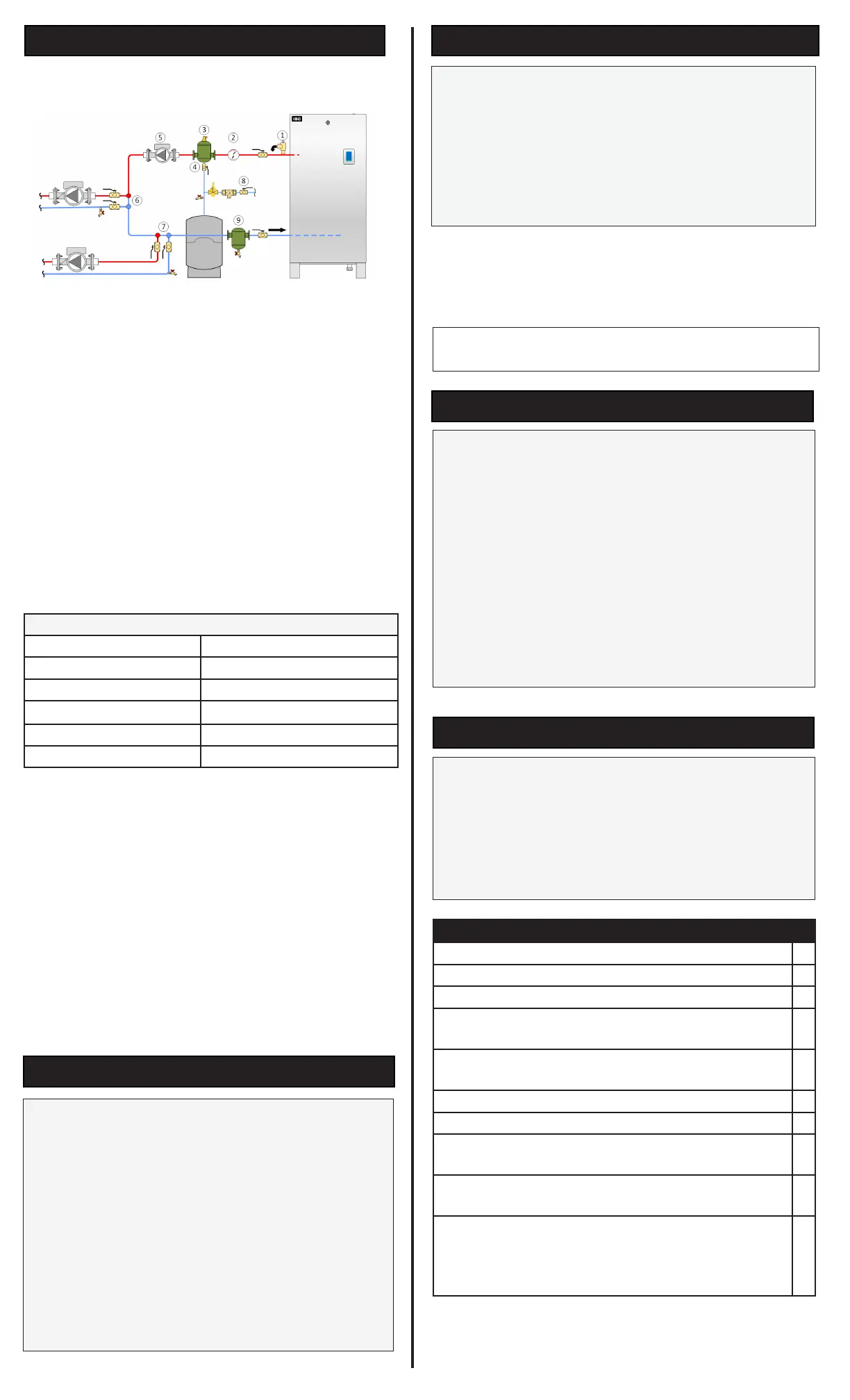
1. Pressure relief valve (shipped with boiler): no isolaon valve
permied between boiler and relief valve
2. Tridicator (shipped with boiler)
3. Microbubble air eliminators
4. Expansion tank connecon
5. Boiler Pump
6. Closely-spaced tees to/from Load 1
7. Closely spaced tees to/from Load 2
8. Fill staon
9. Dirt seperator recommended
 Loading...


