INSTALLATION AND OPERATION INSTRUCTIONS
5-2
HC SERIES BOILERS HC 13-50, HC 23-84, HC 29-106, HC 33-124, HC 20-125, HC 33-160
ELECTRONIC COMPONENTS
This section details the method for troubleshooting the non-standard electronic
components on the boiler including the electronic water pressure sensor and the
temperature sensors.
5.2.1 Temperature Sensors
The resistance of the temperature sensors varies inversely with temperature. To
test, measure the temperature of the sensed environment and compare with the
value derived from the measurement of the resistance (obtained by connecting a
good quality test meter capable of measuring up to 5,000 kΩ (5,000,000Ω) at the
controller end of the sensor lead).
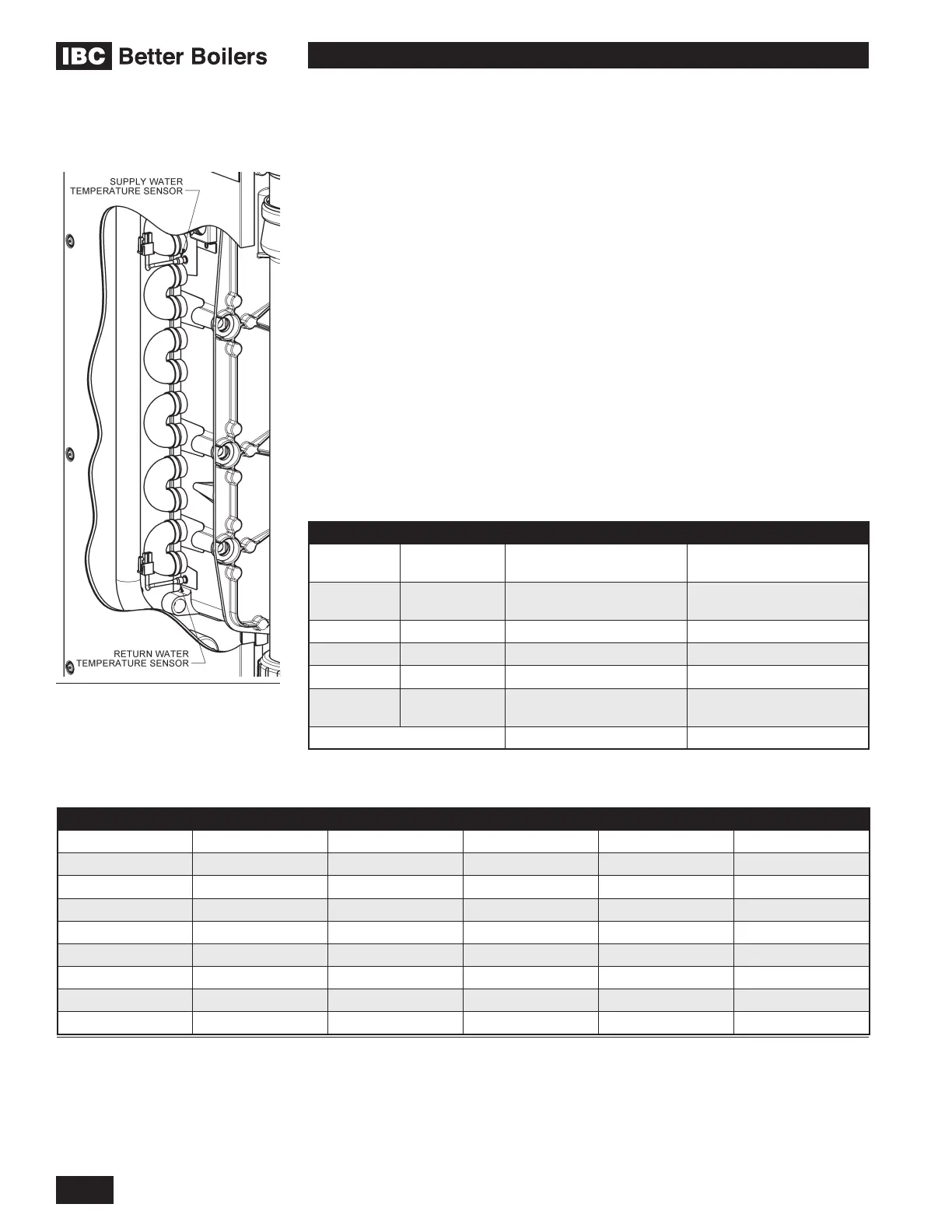
To obtain a resistance reading, remove power to the boiler. For the supply water
and return water temperature sensors, remove the wire leads by disconnecting
their respective Molex connectors. Place multi-meter probes into sensor’s male
Molex connector socket. Do not apply voltage to the sensor (damage may result).
12KΩ Temperature Sensors supplied with boiler. See Table 12 for resistance
values.
SENSOR TYPE PURPOSE LOCATION
S1 NTC 12KΩ Supply Water Temperature Upper Left of Heat
Exchanger
S2 NTC 12KΩ Return Water Temperature Lower Left of Heat
Exchanger
S3 NTC 12KΩ Domestic Hot Water DHW Supply Pipe
S4 NTC 10KΩ Hot Water Tank External Water Heater
S5 NTC 12KΩ Outdoor Sensor Outdoors (North side)
NTC 12KΩ Flue Gas Temperature Bottom of Heat Exchanger
at Flue outlet
Water Pressure Heating Supply Pipe
Temperature and Pressure Sensors
5.2
Return water temperature sensor
TEMPERATURE RESISTANCE TEMPERATURE RESISTANCE TEMPERATURE RESISTANCE
F / C Ω - ohm F / C Ω - ohm F / C Ω - ohm
5F / -15C 76,020 77F / 25C 12,000 149F / 65C 2,752
14F / -10C 58,880 86F / 30C 9,805 158F / 70C 2,337
23F / -5C 45,950 95F / 35C 8,055 167F / 75C 1,994
32F / 0C 36,130 104F / 40C 6,653 176F / 80C 1,707
41F / 5C 28,600 113F / 45C 5,522 185F / 85C 1,467
50F / 10C 22,800 122F / 50C 4,609 194F / 90C 1,266
59F / 15C 18,300 131F / 55C 3,863 203F / 95C 1,096
68F / 20C 14,770 140F / 60C 3,253 212F / 100C 952
Table 12: Temperature Sensor Resistance Values
 Loading...


