Read-in Cycle
1:
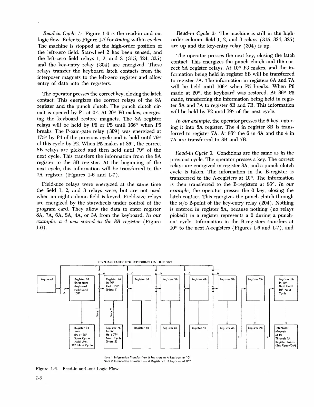
Figure
1-6 is
the
read-in
and
out
logic flow. Refer to
Figure
1-7 for timing
within
cycles.
The
machine
is
stopped
at
the
high-order position of
the
left-zero field.
Starwheel
2 has
been
sensed,
and
the
left-zero field relays 1,
2,
and
3 ( 315, 324, 325)
and
the
key-entry relay ( 304)
are
energized.
These
relays transfer
the
keyboard
latch
contacts from
the
interposer magnets to
the
left-zero register
and
allow
entry
of
data
into
the
registers.
The
operator
presses
the
correct key, closing
the
latch
contact. This energizes
the
correct relays of
the
8A
register
and
the
punch
clutch.
The
punch
clutch cir-
cuit is
opened
by
Pl
at
0°. At 20° P6 makes, energiz-
ing
the
keyboard
restore magnets.
The
8A register
relays will
be
held
by
P6
or
P5
until
166°
when
P5
breaks.
The
P-cam-gate
relay
(309)
was energized
at
175°
by
P4 of
the
previous cycle
and
is
held
until 79°
of this cycle
by
P2.
When
P5
makes
at
86°,
the
correct
BB
relays
are
picked
and
then
held
until
79° of
the
next cycle. This transfers
the
information from
the
8A
register to
the
BB
register.
At
the
beginning
of
the
next cycle, this information will
be
transferred
to
the
7 A register
(Figures
1-6
and
1-
7).
Field-size relays
were
energized
at
the
same time
the
field
1,
2,
and
3 relays were,
but
are
not
used
when
an
eight-column field is keyed. Field-size relays
are energized
by
the
starwheels
under
control of
the
program
card.
They
allow
the
data
to
enter
register
BA,
7
A,
6A, 5A, 4A,
or
3A from
the
keyboard.
In
our
example: a 4 was stored
in
the
BB
register
(Figure
1-6).
Read-in Cycle
2:
The
machine is still
in
the
high-
order
column, field
1,
2,
and
3 relays ( 315, 324, 325)
are
up
and
the
key-entry relay ( 304) is up.
The
operator
presses
the
next key, closing
the
latch
contact. This energizes
the
punch
clutch
and
the
cor-
rect
8A register relays.
At
10° P3 makes,
and
the
in-
formation
being
held
in
register
8B
will
be
transferred
to register 7
A.
The
information
in
registers 8A
and
7 A
will
be
held
until
166°
when
P5 breaks.
When
P6
made
at
20°,
the
keyboard
was restored.
At
86° P5
made,
transferring
the
information
being
held
in
regis-
ter
8A
and
7 A
to
register
BB
and
7B. This information
will
be
held
by
P2 until 79° of
the
next cycle.
In
our example,
the
operator
presses
the
6 key, enter-
ing
it
into 8A register.
The
4
in
register 8B is trans-
ferred
to register 7
A.
At 86°
the
6 in
BA
and
the
4 in
7 A
are
transferred to
BB
and
7B.
Read-in Cycle
3:
Conditions
are
the
same as in
the
previous cycle.
The
operator
presses a key.
The
correct
relays
are
energized
in
register
BA,
and
a
punch
clutch
cycle is taken.
The
information
in
the
B-register is
transferred
to
the
A-registers
at
10°.
The
information
is
then
transferred to
the
B-registers
at
86°.
In
our
example,
the
operator presses
the
0 key, closing
the
latch
contact. This energizes
the
punch
clutch
through
the
N/o
2-point of
the
key-entry relay
(204).
Nothing
is
entered
in
register
BA,
because
nothing
(no
relays
picked)
in
a register represents a 0
during
a
punch-
out
cycle. Information
in
the
B-registers transfers
at
10° to
the
next A-registers
(Figures
1-6
and
1-7),
and
KEYBOARD ENTRY LINE DEPENDING
ON
FIELD
SIZE
Keyboard
Register 8A
Enter from
Keyboard
JI
Held until
158°
Register 88
from
BA
at
86°
Some
Cycle
Held Until
79°
Next
Cycle
~
~
r--1>
~
~
·-
i!
0
z
t--
Register 7A
Register 6A Register 5A
In
10°
Held
158°
(Note
1)
H
>--
~
N
Q)
0
z
Register 78
Register
68
Register
58
In
86°
Held 79°
Next
Cycle
t--
!---'
t----"
(Note
2)
Note
1 Information Transfer from B Registers to A Registers
at
10°
Note
2 Information Transfer from A Registers
to
B Registers
at
86°
Figure 1-6. Read-in
and
-out Logic Flow
1-6
~
Register 4A
Register 3A
Register 2A
Register
lA
In
10°
Held Until
H
,..
r--
10°
Next
Cycle
Register
48
Register
38
Register
28
Interposer
Mognets
at
P5
1---'
1--
f--J
Through
lA
Register Points
(2nd
Read-Out)

 Loading...