through
2A
to
register
BB
through
2B.
The
interposer
magnet
is
energized
at
86°
(PS)
through
the
decode
tree.
The
escape
magnet
is
energized
by
the
closing
of
the
interposer
bail
contacts.
The
escape-armature
contact energizes
the
escape-interlock relays.
The
punch
clutch
is
energized
through
Pl,
the
escape-
interlock relays
and
P2. In our example,
we
punched
a zero
in
card
column
11,
energized
the
interposer 0
magnet,
escaped
to column 12,
and
energized
the
punch
clutch.
Read-out, Punch-out Cycles
4,
5,
6 and
7:
Cycles 4,
5,
6,
and
7
are
identical
to
cycle 3
in
operation. In our
example,
we
punched
a 0
in
column
12,
energized
the
interposer 4 magnet,
and
escaped
to
column 13
during
cycle
4.
During
cycle 5
we
punch
a
4,
energize
the
interposer 6 magnet,
and
escape
to column 14.
In
cycle
6
we
punch
a 6
in
column
14, energize
the
interposer 0
magnet
and
escape
to
column
15.
In
cycle 7
we
punch
a 0
in
column 15, energize a 7 interposer magnet,
and
escape to column 16.
Read-out, Punch-out Cycle
8:
During
this cycle,
the
information set
up
in
cycle 7 is
punched,
the
last digit
is
transferred from
the
register 2B to register IA.
The
interposer
magnet
is
energized
to
allow
the
last digit
t-0
be
punched
on
the
next cycle.
At
10°
the
informa-
tion
in
register 2B is
transferred
into
register IA.
At
Cycle
Key
6A
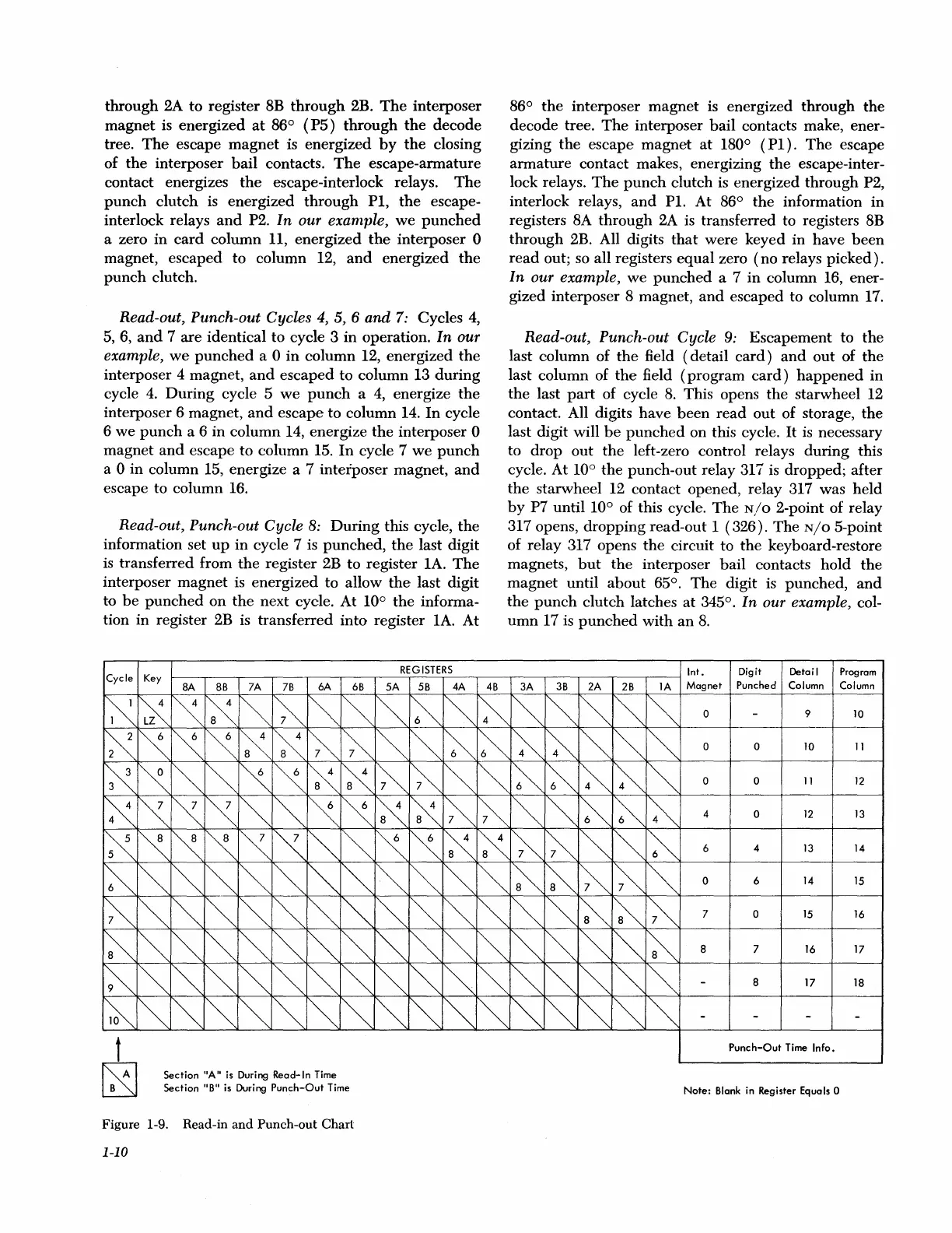
Section "A"
is
During Read-In
Time
Section
"B"
is During
Punch-Out
Time
6B
Figure 1-9. Read-in
and
Punch-out
Chart
1-10
REGISTERS
SA
SB
4A
4B
86°
the
interposer
magnet
is energized
through
the
decode
tree.
The
interposer
bail
contacts make, ener-
gizing
the
escape
magnet
at
180°
(Pl).
The
escape
armature
contact
makes, energizing
the
escape-inter-
lock relays.
The
punch
clutch is energized
through
P2,
interlock relays,
and
Pl.
At 86°
the
information
in
registers 8A
through
2A is transferred to registers 8B
through
2B. All digits
that
were
keyed in
have
been
read
out; so all registers
equal
zero
(no
relays
picked).
In our example,
we
punched
a 7
in
column 16, ener-
gized interposer 8 magnet,
and
escaped to
column
17.
Read-out, Punch-out Cycle
9:
Escapement
to
the
last column of
the
field ( detail
card)
and
out
of
the
last column of
the
field
(program
card)
happened
in
the
last
part
of cycle
8.
This opens
the
starwheel 12
contact. All digits
have
been
read
out
of storage,
the
last digit will
be
punched
on
this cycle.
It
is necessary
to
drop
out
the
left-zero control relays
during
this
cycle. At 10°
the
punch-out
relay 317 is
dropped;
after
the
starwheel 12 contact opened, relay 317 was
held
by
P7
until
10° of this cycle.
The
N/o
2-point of relay
317 opens,
dropping
read-out I
(326).
The
N/o
5-point
of relay 317 opens
the
circuit to
the
keyboard-restore
magnets,
but
the
interposer bail contacts
hold
the
magnet
until
about
65°.
The
digit is
punched,
and
the
punch
clutch latches
at
345°. In our example, col-
umn
17 is
punched
with
an
8.
Int.
Digit
Detail Program
3A
3B
2A
2B
lA
Magnet
Punched
Column Column
0
9
lO
0 0
lO
ll
0 0
11
12
4
0
12
13
6 4
13
14
0 6
14
lS
7 0 lS
16
8 7
16 17
8
17
18
Punch-Out
Time
Info.
Note:
Blank
in Register Equals 0

 Loading...