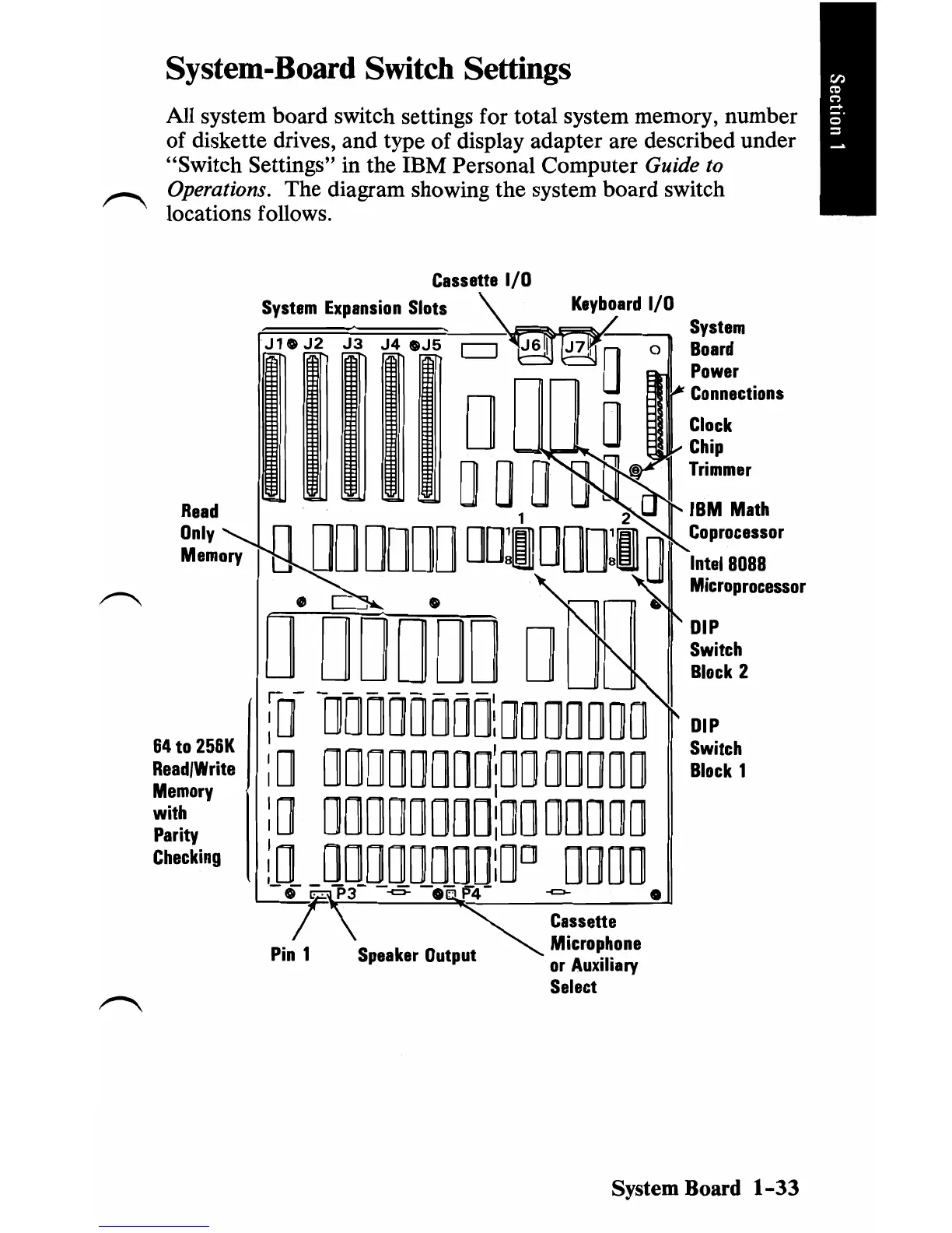
System-Board Switch Settings
All system board switch settings for total system memory, number
of
diskette drives, and type of display adapter are described under
"Switch Settings" in the IBM Personal Computer
Guide
to
Operations. The diagram showing the system board switch
locations follows.
Cassette
I/O
System
Expansion
Slots
System
J 1 0
J2
J3
J4
OJ5
o
Board
Power
Connections
D
Clock
Trimmer
o0 0 0
Chip
11
Read
IBM
Math
Only
Coprocessor
Memory
Cl
Intel
8088
000000
ODIDDOIO
Microprocessor
DIP
Switch
D°
DDD"DO
ON
Block
2
DIP
64
to
256K
Switch
Read/Write
Block
1
:0-
-ODOOOODOlOODDDDD
: 0
OOOODDDD\DODDDDD
Memory
with
:0
00000000:0000000
Parity
Checking
;0
00000000:0
0
DODD
-0-
qP3-
--5
-Oap4-
-c:>-
•
T\
~
Cassette
...
~
Microphone
Pin
1
Speaker
Output
or
Auxiliary
Select
System Board
1-33
 Loading...