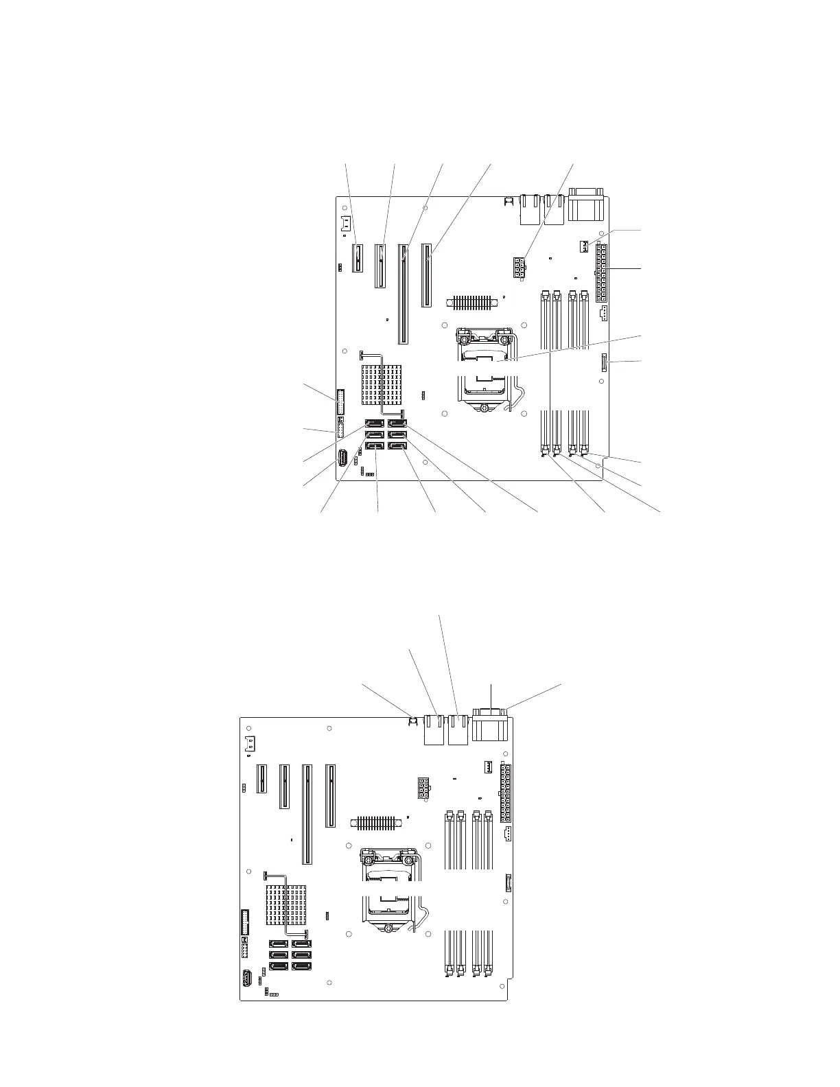
System-board internal connectors
The following illustration shows the internal connectors on the system board.
Microprocessor
DIMM 1 Slot
DIMM 2 Slot
DIMM 3 Slot
DIMM 4 Slot
Battery
DIMM 1
DIMM 2
DIMM 3DIMM 4
SATA 2 S ATA 1 SATA 0SATA 3SATA 4
SATA 5
Slot 1
PCI
Main Power
System fan
connector
Slot 2
PCI
Slot 3
PCI
Slot 4
PCI
Microprocessor
Front USB
connector
Front-panel
connector
Power
USB tape
System-board external connectors
The following illustration shows the external connectors on the system board.
Microprocessor
DIMM 1 Slot
DIMM 2 Slot
DIMM 3 Slot
DIMM 4 Slot
Video
Serial (COM1)
NMI button
Ethernet connector 2/
USB connectors 3&4
Ethernet connector 1/
USB connectors 1&2
Chapter 2. Installing optional devices 19
 Loading...


