16
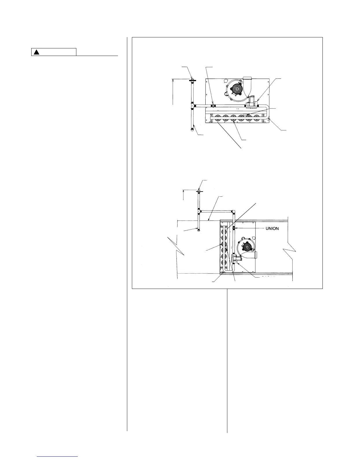
FIGURE 12
GAS PIPING INSTALLATION
UPFLOW & DOWNFLOW
GAS SUPPLY AND PIPING
GAS SUPPLY
THIS FURNACE IS EQUIPPED AT
THE FACTORY FOR USE ON
NATURAL GAS ONLY. CONVERSION
TO LP GAS REQUIRES A SPECIAL
KIT SUPPLIED BY THE
DISTRIBUTOR OR MANUFACTURER.
MAILING ADDRESSES ARE LISTED
ON THE FURNACE RATING PLATE,
PARTS LIST AND WARRANTY.
FAILURE TO USE THE PROPER
CONVERSION KIT CAN CAUSE FIRE,
CARBON MONOXIDE POISONING,
EXPLOSION, PROPERTY DAMAGE,
PERSONAL INJURY OR DEATH.
See the conversion kit index supplied
with the furnace. This index identifies
the proper LP Gas Conversion Kit
required for each particular furnace.
IMPORTANT: Any additions, changes
or conversions required for the furnace
to satisfactorily meet the application
should be made by a qualified installer,
service agency or the gas supplier,
using factory-specified or approved
parts. In the commonwealth of
Massachusetts, installation must be
performed by a licensed plumber or gas
fitter for appropriate fuel.
IMPORTANT: Connect this furnace only
to gas supplied by a commercial utility.
IMPORTANT: A U.L. recognized
fuel gas and CO detector(s) are
recommended in all applications,
and their installation should be in
accordance with the detector
manufacturer’s recommendations
and/or local laws, rules, regulations or
customs.
GAS PIPING
Install the gas piping according to all
local codes, state codes and regulations
of the utility company, whichever holds
jurisdiction.
If possible, run a separate gas supply
line directly from the meter to the
furnace. Consult the local gas company
for the location of the manual main shut-
off valve. The gas line and manual gas
valve must be adequate in size to
prevent undue pressure drop and
never smaller than the pipe size to
the combination gas valve on the
furnace. Refer to Table 2 for the recom-
mended pipe size for natural gas and
Table 3 for LP gas pipe sizes.
IMPORTANT: It is permissible to run
flexible gas connector inside the unit to
!
WARNING
HORIZONTAL
a piece of black pipe. If local codes
allow the use of a flexible gas appliance
connector, always use a new listed
connector. Do not use a connector
which has previously serviced another
gas appliance. Massachusetts law
limits flexible gas connectors to a
maximum of 36”.
Install a ground joint union outside
the cabinet to easily remove the
control valve assembly. Install a
manual shut-off valve in the gas line
outside the furnace casing. The valve
should be readily accessible to turn the
gas supply on or off. Install a drip leg in
the gas supply line as close to the
furnace as possible. Always use a pipe
compound resistant to the action of
liquefied petroleum gases on all
threaded connections.
IMPORTANT: When making gas pipe
connections, use a back-up wrench to
prevent any twisting of the control
assembly and gas valve.
Any strains on the gas valve can
change the position of the gas orifices
in the burners. This can cause erratic
furnace operation.
IMPORTANT: ENSURE that the
furnace gas control valve not be
subjected to high gas line supply
pressures.
DISCONNECT the furnace and its
individual shut-off valve from the gas
supply piping during any pressure
testing that exceeds 1/2 PSIG
(3.48 kPa).
MANUAL GAS VALVE
(IN CLOSED POSITION)
MANUAL GAS VALVE
(IN CLOSED POSITION)
FLAME SENSOR
FLAME SENSOR
4 TO 5 FEET
ABOVE FLOOR
REQ’D BY SOME
UTILITIES
4 TO 5 FEET
ABOVE FLOOR
REQ’D BY SOME
UTILITIES
UNION
GAS VALVE
IGNITION OF PILOT
MANIFOLD
MANIFOLD
IGNITION OF PILOT
GAS VALVE
BURNERS
DUCT
DRIP LEG
DRIP LEG
BURNERS
 Loading...