62
■
AATT--118800 iinntteerrnnaall sswwiittcchh ddeessccrriippttiioonn
The optional AT-180 has 3 operating conditions for
HF band operation. Select a suitable condition
according to your antenna system.
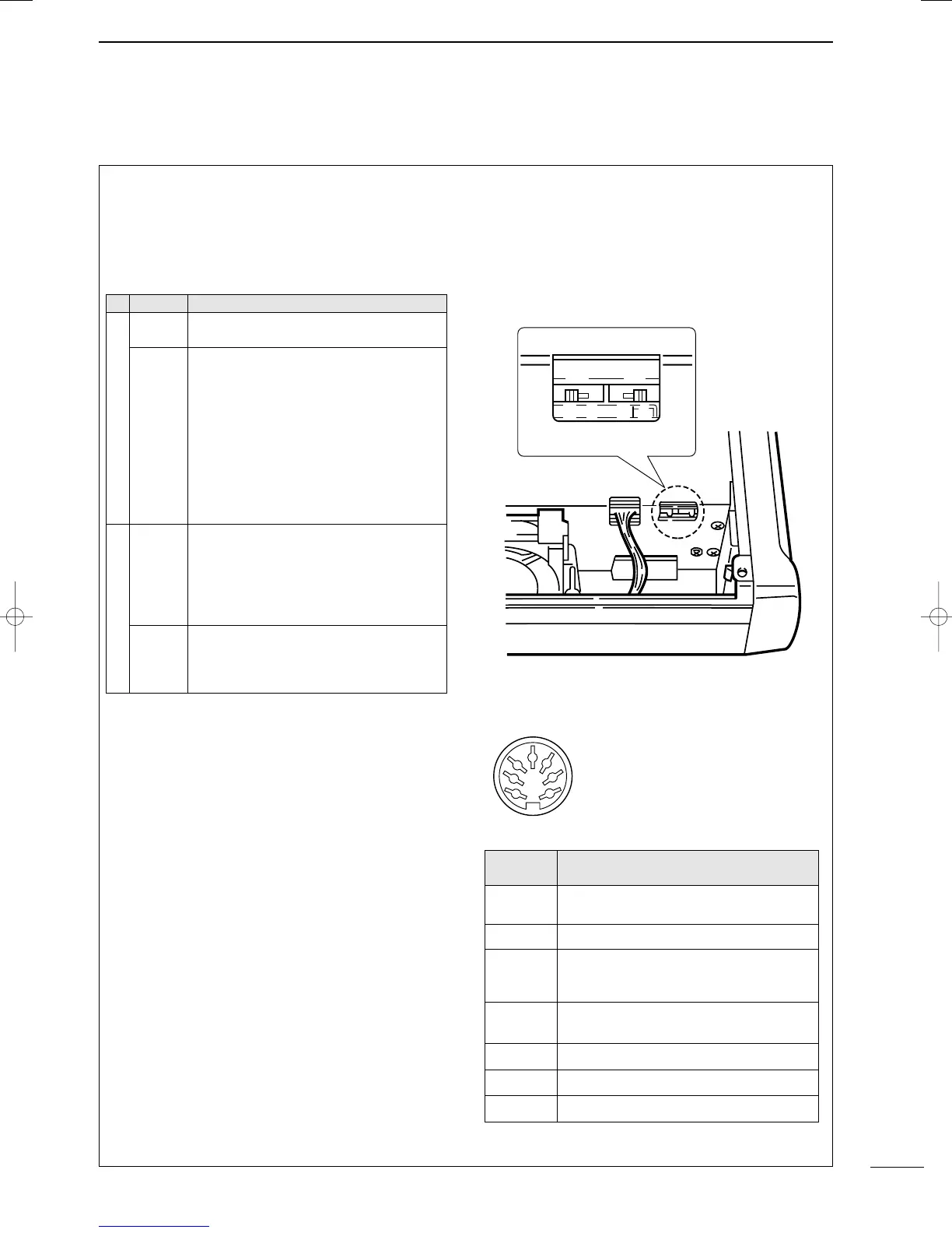
➀ Remove the top cover of the AT-180.
➁ Set the tuner switches to the desired positions
according to the table below.
•
SSppeecciiffiiccaattiioonnss ffoorr tthhee AATT--118800
• Frequency coverage : 1.9 – 54 MHz
• Input impedance : 50 Ω
• Maximum input : 120 W
power
• Minimum tuning : 8 W
power
• Matching impedance : 16.7–150 Ω (HF band)
range 20 –125 Ω (50 MHz band)
• Tuning accuracy : Less than SWR 1.5:1
• Insertion loss : Less than 1.0 dB
(after tuning)
• Power supply : 13.8 V DC/1 A (supplied from
requirements the transceiver’s ACC socket)
• Dimensions (mm/in) : 167(W) × 58.6(H) × 225(D)
6
9
⁄16(W) × 2
5
⁄17(H) × 8
7
⁄8(D)
• Weight : 2.4 kg; 5 lb 4 oz
• Supplied accessories : coaxial cable (1 m),
ACC cable (DIN 13 pins)
•
AATT--118800 iinnssiiddee ttoopp ccoovveerr
•
CCoonnnneeccttoorr iinnffoorrmmaattiioonn ffoorr AACCCC((22)) ssoocckkeett
S2 S1
DC BA
ACC 2
1
2
3
4
76
5
PPIINN NNOO..//
NNAAMMEE
DDEESSCCRRIIPPTTIIOONN
➀ 8 V
Regulated 8 V output.
(10 mA max.)
➁ GND
Connects to ground.
➂ SEND
Input/output pin.
Goes to ground when transmitting (20 mA
max). When grounded, transmits.
➃ BAND
Band voltage output.
(Varies with amateur band; 0 to 8.0 V).
➄ ALC
ALC output voltage (–4 to 0 V).
➅ NC
No connection.
➆ 13.8V
13.8 V output when power is ON (1 A max).
SSWW PPoossiittiioonn
OOppeerraattiioonn
S1
A
(default)
The tuner operating condition is set by S2
described below.
B
THROUGH INHIBIT
The tuner tunes the antenna even when
the antenna has poor SWR (up to VSWR
3:1 after tuning). In this case, manual tun-
ing is necessary each time you change the
frequency although the tuner automatical-
ly starts tuning when the VSWR is higher
than 3:1. This setting is called “through
inhibit,” however, the tuner is set to
“through” if the VSWR is higher than 3:1
after tuning.
S2
C
TUNER SENSITIVE CONDITION
The tuner tunes each time you transmit
(except SSB mode). Therefore, the lowest
SWR is obtained at any given time.
For SSB mode, the same condition as the
“D” position.
D
(default)
NORMAL CONDITION
The tuner tunes when the SWR is higher
than 1.5:1. Therefore, the tuner activates
only when tuning is necessary.
10
OPTIONAL INSTALLATIONS/SETTINGS
IC-706MKIIG.qxd 02.3.27 13:53 Page 62
 Loading...