1-1-32Kamiminami,Hirano-ku,Osaka547-0003,Japan
A-7022D-3EX-q PrintedinJapan
©2012IcomInc.
¤3 Received Call Log
The transceiver automatically stores up to 50 distress mes-
sages and 50 other messages, and they can be used as a
supplement to your logbook.
•While in thenormaloperatingmode,“ ” blinks in the upper
right corner of the LCD when there is an unread message.
Push [LOG] to enter “RCVD CALL LOG” in the DSC CALLS q
menu, or you can enter it through the Menu screen.
Select “Distress” or “Others.” w
•TheDistressmessagesarestoredin“Distress.”
•ThemessagesotherthantheDistressarestoredin“Others.”
•“ ” appears when there are unread messages.
•“ ” appears when there are no unread messages.
•Noiconappearswhentherearenomessages.
Select the desired message. e
•Themessageintheunopenedlehasnotbeenread.
Rotate Dial to scroll the message contents. r
To delete the displayed message, push [DEL]. t
•Aconrmationscreenappears,thenpush[OK]todelete.
Push [EXIT] to return to the normal operating mode. y
¤5 DSC Settings
Automatic Acknowledgement D
Enter q
either “INDIVIDUAL ACK,” “POSITION ACK” or “TEST
ACK” in the DSC Settings menu.
Rotate Dial w
to select “Auto TX” or “Manual TX,” then push
[ENT].
•Push[BACK]tocancelandreturntotheDSCSettingsmenu.
Push [EXIT] to return to the normal operating mode. e
Channel 16 Switch function D
Enter “CH 16 SWITCH” q
in the DSC Settings menu
.
Rotate Dial to set the Channel 16 Switch function to “Auto w
(NoDelay),”“10SecondDelay”or“OFF
,” then push [ENT].
•Push[BACK]tocancelandreturntotheDSCSettingsmenu.
Push [EXIT] to return to the normal operating mode. e
DSC Data Output D
Enter “DSC DATA OUTPUT” q
in the DSC Settings menu
.
Rotate Dial to set the DSC Data Output function to “All Sta- w
tion,” “List Station” or “OFF
,” then push [ENT].
•Push[BACK]tocancelandreturntotheDSCSettingsmenu.
Push [EXIT] to return to the normal operating mode. e
Alarm D
Enter “ALARM” q
in the DSC Settings menu
.
Rotate Dial to select w
the status, then push [ENT].
•Push[BACK]tocancelandreturntotheDSCSettingsmenu.
•“Safety,”“Routine,”“Warning,”“Self-Terminate”and“Discrete”
are selectable. (default: ON )
Rotate Dial to set the Alarm setting to “ON” or “OFF.” e
Push [EXIT] to return to the normal operating mode. r
Channel 70 Squelch level D
Enter“CH70SQLLEVEL” q
in the DSC Settings menu
.
Rotate Dial to adjust the squelch level until the noise just w
disappears, then push [ENT].
•Push[BACK]tocancelandreturntotheDSCSettingsmenu.
Push [EXIT] to return to the normal operating mode. e
DSC Loop Test D
Enter “DSC LOOP TEST” q
in the DSC Settings menu
.
Push [ENT] to start the DSC loop test. w
•Push[BACK]tocancelandreturntotheDSCSettingsmenu.
•WhenthetransmitDSCandreceiveDSCsignalsarematched,
“OK” appears.
Push [EXIT] to return to the normal operating mode. e
If “NG” appears in step w, either or both TX and RX DSC
circuits has a problem. In that case, you will have to send
the transceiver to your nearest dealer for repair.
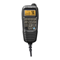
¤4 Transmitted Call Log
Thetransceiverautomaticallystoresupto50transmittedcalls,
and the logs can be used as a supplement to your logbook.
Enter “TX CALL LOG” in the DSC CALLS menu. q
Select the desired message. w
Rotate Dial to scroll the message contents. e
To delete the displayed message, push [DEL]. r
•Theconrmationscreenappears,thenpush[OK]todelete.
Push [EXIT] to return to the normal operating mode. t
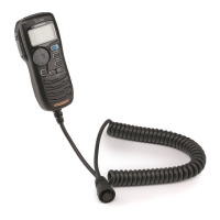
Receiving a Test Call D
Push [ALARM OFF] to stop the alarm and the blinking back- q
light.
•If [ALARM OFF] is not pushed within 2 minutes, the next
screen may appear, depending on the call Category.
Push a softkey to select your desired action. w
[IGN]
Push to ignore the call and return to the normal operating
mode.
[INFO]
Push to display the Received Call information. (
See ¤3
)
[ACK]
Push to display the “TEST ACK” screen to reply to the call.
(
See ¤1
)
When “TEST ACK” is set to “Auto TX,” the transceiver
automatically replies to the call. In that case, both the TX
and RX calls are stored in the Transmitted and Received
Call Logs.
Receiving a Test Acknowledgement Call D
Push [ALARM OFF] to stop the alarm and the blinking back- q
light.
•If [ALARM OFF] is not pushed within 2 minutes, the next
screen may appear, depending on the call Category.
Push [EXIT] to return to the normal operating mode. w
¤2 Receiving DSC calls (Continued)
¤6 Intercom operation
ThisfunctionisnotavailablewiththeIC-M400BB.
Push [INCM] to enter the Intercom mode. q
Hold down [INCM CALL] to sound the intercom beeps. w
•Thetransceiverandthecommandmicrophonesoundbeeps
while holding down [INCM CALL].
•“CALL”appears.
After releasing [INCM CALL], hold down [PTT] and speak e
into the microphone at a normal voice level.
•“TALK”appearsonthecaller’sdisplay,or“LSTN”appearson
the listener’s display.
•To adjust the HM-195’s intercom volume level, rotate [VOL/
SQL](Dial)ontheHM-195.
After releasing [PTT] you can hear the response through r
the speaker.
To return to the normal operating mode, push [EXIT]. t
¤7 RX Speaker function
Push [RX q ] to enter the RX Speaker mode.
•TheRXSpeakervolumeleveladjustmentscreenisdisplayed.
Rotate Dial or push [ w Y]/[Z]/[Ω]/[≈] to adjust the RX Speak-
er volume level, and then push [ENT].
•“RX ” appears.
To return to normal operating mode, push [RX e ].
•“RX ” disappears.
¤8 PA (Public Address) function
Push [PA] to enter the Public Address mode. q
Hold down [PTT] and speak at a normal voice level. w
•Whileholdingdown[PTT],thescreenbelowisdisplayed.
•ToadjustthePAvolumelevel,rotateDial.
Push [EXIT] to return to normal operating screen. e
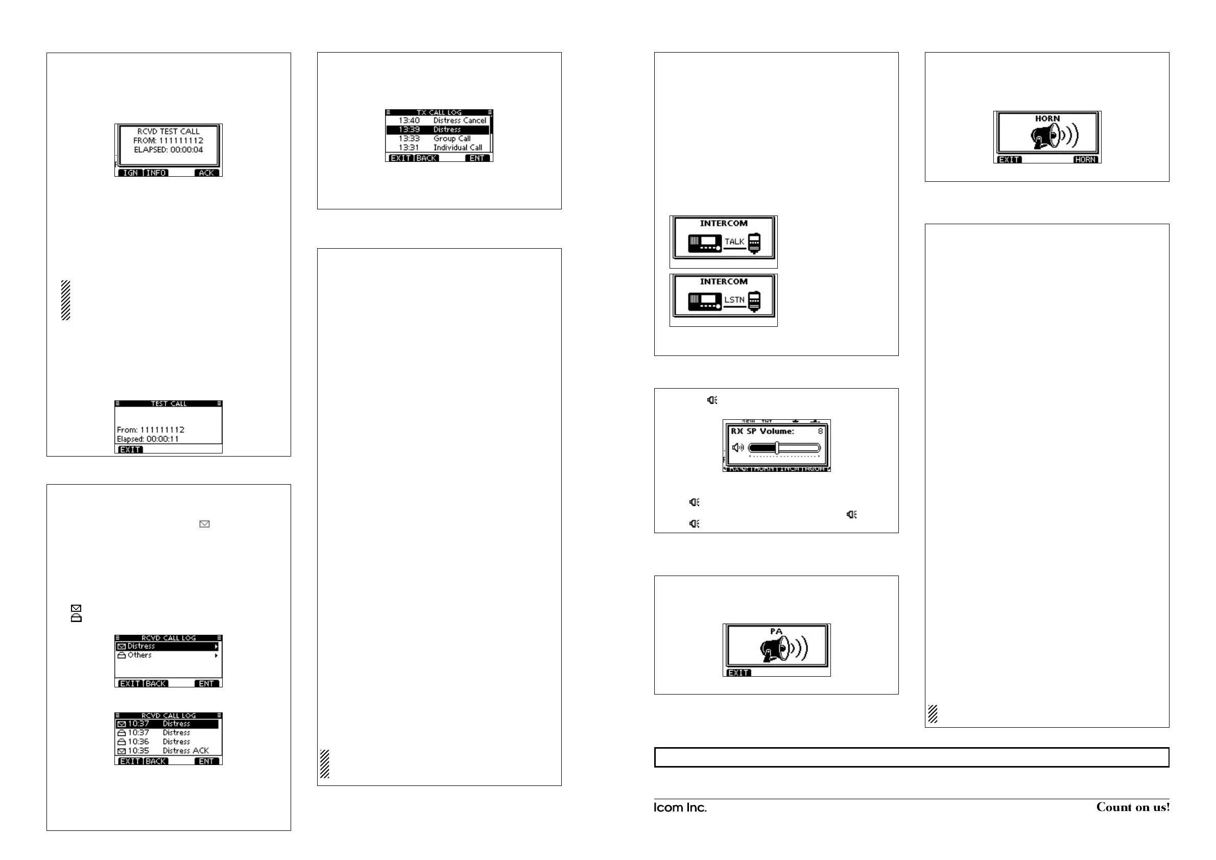
¤9 Horn function
Push [HORN] to enter the Horn mode. q
Hold down [HORN] to sound a horn. w
•Whileholdingdown[HORN],thehornsounds,andthescreen
below is displayed.
•Toadjustthehornvolumelevel,rotateDial.
Push [EXIT] to return to the normal operating screen. e
‹0 Menu screen operation
The Menu screen is used to change the transceiver’s functions
and the microphone’s own functions, send DSC calls or show
the programmed MMSI and ATIS*
1
codes and GPS informa-
tion*
2
.
*
1
Appears only when the transceiver is the Dutch or German ver-
sion.
*
2
AppearsonlywhenaGPSreceivercompatiblewithNMEA0183
ver.2.0or3.01isconnectedtothetransceiver.
These instructions are for only the microphone’s own func-
tions. Refer to the transceiver’s manual for the settings of
the other functions. (Some functions cannot be selected
fromtheHM-195.)
D
Entering the Menu screen and operation
Push [MENU]. q
Rotate Dial or push [ w ∫]/[√] to select the root item, and then
push [ENT].
Rotate Dial or push [ e ∫]/[√] to select the desired item, and
then push [ENT].
Rotate Dial or push [ r ∫]/[√] to select the option, and then
push [ENT] to set it.
t
Push[EXIT]toexittheMenuscreen.
•Push[CLEAR]or[BACK]toreturntothepreviousscreen.
• Backlight
ThefunctiondisplayandkeysoftheHM-195canbebacklitfor
better visibility under low light conditions.
Thebacklightcanbesetto7levelsandOFF. (Default:7)
• Display contrast
ThecontrastoftheHM-195’sfunctiondisplaycanbeadjusted
in8steps.
Level1isthelowestcontrast,andlevel8isthehighestcon-
trast. (Default:5)
• Key Beep
You can turn OFF beep tones for silent operation, or you can
turn ON the tones to have confirmation beeps sound when a
key is pushed. (Default: ON)
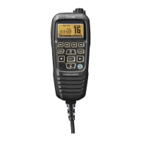
• COMMANDMIC Speaker
TheHM-195’sexternalspeakercanbeusedinsteadofthein-
ternal speaker. (Default: Internal Speaker)
Regardless of this setting, the transceiver’s microphone
speaker is ON.
On the caller’s display
On the listener’s display
When “Distress” is selected in step w.
+See “Instructions q” (z to ⁄5) or “Instructions w” (⁄6 to ¤1) for other functions.
 Loading...