SECTION
3
CIRCUIT DESCRIPTION
3-1
RECEIVER CIRCUITS
3-1-1
ANTENNA SWITCHING CIRCUIT
(MAIN UNIT)
The
antenna switching circuit functions as a low-pass
filter while
receiving and
a
resonator circuit while trans-
mitting. The circiut
does
not allow transmit signals
to
enter receiver circuits.
Received signals enter the antenna
connector and then
pass
through the low-pass filter (L9-L12, C54-C62), the
X/4 type
antenna switching circuit (D7, D16, D17, L19,
L20, C107,
Cl
08)
and are then applied to the
RF ampli-
fier
(Q20).
3-1-2
RF AND 1st
MIXER CIRCUITS
(MAIN UNIT)
The 1st
mixer circuit converts the received
signal
to a
fixed frequency
of the
1st
IF signal with
a
PLL
output
frequency. By
changing the PLL frequency, only the
desired frequency
will
be passed through a pair of crystal
filters at the next stage of
the 1
st
mixer.
The signals from the antenna switching circuit
are
passed
through the
tunable
band-pass
filter (D14, LI
8)
and
amplified at the
RF amplifier
(Q20).
The amplified signals
are
again
passed
through the tunable band-pass
filter
(DIO, D13, D31, L16,
L17, L26) and applied to the 1st
mixer
(Q19).
The signals are then mixed
with
a 1st LO
signal coming from the VCO
circuit
to
produce
a
17.2 MHz
1st
IF signal. The 1st
IF signal is passed through a pair
of crystal
filters (FI1) and is then applied to the IF ampli-
fier
(Q1
8).
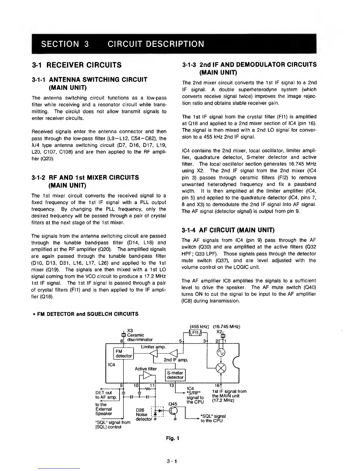
•
FM DETECTOR
and SQUELCH CIRCUITS
3-1-3
2nd IF AND
DEMODULATOR CIRCUITS
(MAIN UNIT)
The 2nd
mixer circuit converts the 1st IF signal to a 2nd
IF signal. A double
superheterodyne system
(which
converts
receive signal twice) improves the image
rejec-
tion ratio and obtains
stable receiver gain.
The
1st
IF signal from the
crystal filter (FI1) is amplified
at Q18 and
applied
to a
2nd
mixer
section
of IC4 (pin
16).
The signal is then mixed with a 2nd
LO signal for conver-
sion
to a
455 kHz 2nd IF signal.
IC4 contains the 2nd
mixer, local oscillator, limiter
ampli-
fier,
quadrature detector, S-meter
detector and active
filter. The local oscillator section
generates 16.745 MHz
using X2. The 2nd IF signal
from the 2nd mixer (IC4
pin
3)
passes
through ceramic filters (FI2) to
remove
unwanted heterodyned frequency
and fix a passband
width. It Is then
amplified
at
the limiter amplifier (IC4,
pin
5)
and applied to the
quadrature detector (IC4, pins
7,
8 and X3) to
demodulate the 2nd IF
signal
into
AF signal.
The AF signal (detector signal) is output
from
pin
9.
3-1-4
AF CIRCUIT
(MAIN UNIT)
The AF signals
from IC4 (pin
9)
pass through the
AF
switch
(Q30)
and are amplified at
the active filters
(Q32
HPF;
Q33
LPF). Those
signals pass through the
detector
mute
switch
(Q37),
and are ievel adjusted
with the
volume control on the
LOGIC unit.
The AF amplifier IC8 amplifies
the signals
to a
sufficient
level to drive the
speaker. The AF mute switch
(Q40)
turns ON
to cut
the signai to be input to the
AF amplifier
(108)
during transmission.
Fig.
1
3-1
 Loading...