2-conductor 3.5 (d) mm (
1
⁄8″) plug
to [REMOTE] jack
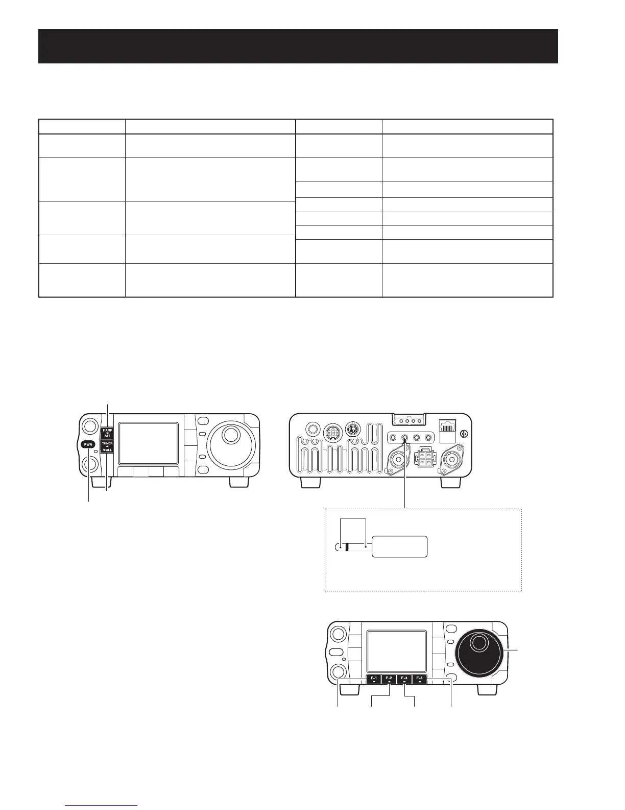
Rear panel
Front panel
JIG plug
Shorten the both terminals
[P.AMP/ATT]
[TUNER/CALL]
[PWR]
KEY ACC DATA
MIC
ANT2 ANT1
DC 13.8V
GND
4 - 1
SECTION 4 ADJUSTMENT PROCEDURES
4-1 PREPARATION
Some adjustment must be performed on the adjustment mode.
M REQUIRED TEST EQUIPMENT
EQUIPMENT GRADE AND RANGE EQUIPMENT GRADE AND RENGE
DC power supply
Output voltage : 13.8 V DC
Current capacity : 30 A or more
Distortion meter
Frequency range : 1 kHz ±10 %
Measuring range : 1–100 %
RF power meter
(treminated type)
Measuring range : 0.5–200 W
Frequency range : 1.8–500 MHz
Impedance : 50 Ω
SWR : 1.2 : 1 or better
Oscilloscope
Frequency range : DC–100 MHz
Measuring range : 0.01–10 V
Digital multimeter Imput impeadance : 10 MΩ/DC or more
AC millivoltmeter Measuring range : 10 mV to 10 V
Frequency counter
Frequency range : 0.1–500 MHz
Frequency accuracy : ±1 ppm or better
Sensitivity : 100 mV or better
DC voltmeter Input impedance : 50 kΩ/V DC or more
DC ammeter Measuring capability : 5 A/30 A
RF voltmeter
Frequency range : 0.1–500 MHz
Measuring range : 0.01–10 V
Audio generator
Frequency range : 300–3000 Hz
Measuring range : 1–500 mV
Standard signal
generator (SSG)
Frequency range : 0.1–500 MHz
Output level : 0.1 µV to 32 mV
(–127 to –17 dBm)
External speaker
Input impedance : 8 Ω
Capacity : 5 W or more
M ENTERING THE ADJUSTMENT MODE
q Turn the transceiver’s power OFF.
w Connect the JIG plug (see illustration below) to [REMOTE] jack on the rear panel.
e While pushing and holding [P.AMP/ATT] and [TUNE/CALL], turn the transceiver power ON.
NOTE: Exiting from the adjustment mode when the transceiver's power is OFF.
M
OPERATING ON THE ADJUSTMENT MODE
• Enter DDS adjustment mode. : Push [F-1 (REF)]
• Enter TX adjustment mode. : Push [F-2 (TX)]
• Enter RX adjustment mode. : Push [F-3 (RX)]
• Store the set value. : Push [F-4 (SET)]
• Adjust the value. : Rotate [DIAL]
CAUTION:
Connect a dummy load to the antenna con-
nectors during the transmitter adjustment,
when the adjustment condition does not re-
quire a test equipment.
[F-1(REF)]
[F-3 (RX)]
[DIAL]
[F-2 (TX)]
[F-4 (SET)]
 Loading...