3 - 1
SECTION 3 CIRCUIT DESCRIPTION
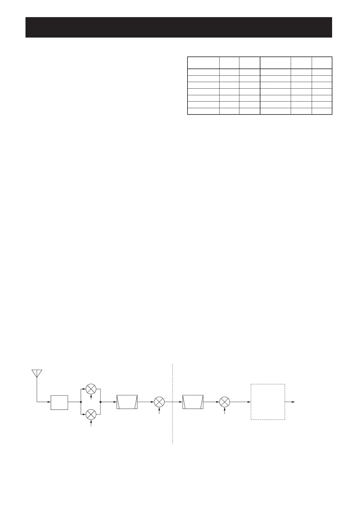
Receiver construction
1st LO B
1st LO A
LPF or
BPF
2nd LO
64.0 MHz
Crystal
filter
FI1701
1st mixer A
Q1203–Q1206
1st mixer B
Q1003–Q1006
2nd mixer
D1752
3rd LO
491 kHz
3rd mixer
IC151
64.455 MHz
0.03–60.0 MHz
Ceramic
filter
FI111
455 kHz
to squelch gate
(IC301)
36 kHz
DSP-A
board
RF-B UNIT MAIN-A UNIT
Band
Control
signal
Input
diode
Band
Control
signal
Input
diode
0.03–1.6 MHz B0 D801 11–15 MHz B7 D551
1.6–2 MHz B1 *D3201 15–22 MHz B8 D602
2–3 MHz B2 *D3301 22–30 MHz B9 D651
3–4 MHz B3 *D3401 30–50 MHz B10W D701
4–6 MHz B4 *D3501 50–54 MHz B10 D751
6–8 MHz B5 *D3601 54–60 MHz B10W D701
8–11 MHz B6 D501
3-1 RECEIVER CIRCUIT
3-1-1 RF SWITCHING CIRCUIT
(CTRL-A AND RF-B UNITS)
The RF switching circuit leads receive signals to bandpass
fi lters from an antenna connector while receiving. However,
the circuit leads the signal from the RF power amplifier to
the antenna connector while transmitting.
RF signals from [ANT 1] or [ANT 2] pass through the an-
tenna selector (RL3), transmit/receive switching relays (RL1,
RL2, RL4), and low-pass fi lter (L27, L28, C63–C66, C105),
and are then applied to the RF-B unit via J101 (RF-B unit).
The signals from the CTRL-A unit either bypass or pass
through the 6 dB (RF-B unit, R102,
R106, R111, RL102)
and/or 12 dB (RF-B unit, R112, R113, R114, RL103)
attenuators via the antenna selector (RL101). By selecting
the attenuators, 0 (bypass), 6, 12 and 18 dB attenuations
are obtained. The signals are then applied to the RF fi lters.
When the [RX ANT] is selected, the RF signals are passed
through the low-pass filter (RF-B unit, L101, L102, C101
–C105), then applied to the antenna selector (RF-B unit,
RL101).
3-1-2 RF BANDPASS FILTER CIRCUIT
(RF-B UNIT AND BPF-A BOARD)
RF bandpass fi lters pass only the desired band signals and
suppress any undesired band signals. The RF circuit has 11
bandpass fi lters and 1 low-pass fi lter.
(1) 0.03–1.6 MHz (RF-B UNIT)
The signals pass through the low-pass filter (L801–L802,
C802, C805–C807), attenuator (R801–R803), and are then
applied to the RF amplifi ers (Q1001, Q1002).
(2) 1.6–60 MHz (RF-B UNIT AND BPF-A BOARD)
The signals pass through the band switch (D104) and high-
pass filter (L251–L253, C251, C252, C271–C274) to sup-
press excessively strong signals below 1.6 MHz. The fi ltered
signals are applied to one of 11 bandpass fi lters on the table
at right above, and then applied to or bypassed the pre-
amplifi er circuit.
3-1-3 PRE-AMPLIFIER CIRCUITS (PRIAMP BOARD)
The IC-756PROIII has 2 gain levels of pre-amplifi er circuits.
One has 10 dB gain for the 1.8–21 MHz bands and the other
one has 16 dB gain for the upper 24 MHz bands.
When the [P.AMP] switch is set to [P.AMP 1] or [P.AMP
2], the signals are applied to the pre-amplifier 1 (Q4201,
Q4202) or pre-amplifi er 2 (Q4302) circuit, respectively. Pre-
amplifi ed or bypassed signals are applied to the RF amplifi er
circuits (RF-B unit; Q1001, Q1002 or Q1201, Q1202).
3-1-4 RF AMPLIFIER AND 1ST MIXER CIRCUITS
(RF-B UNIT)
The 1st mixer circuit mixes the receive signals with the 1st
LO signal to convert the receive signal frequencies into a
64.455 MHz 1st IF signal. The IC-756PROIII has two 1st
mixer circuits for the dualwatch function.
The signals from the pre-amplifier circuit, or signals which
bypass the pre-amplifi ers, are divided at L902, L903. Each
signal is applied to a 60 MHz cut-off low-pass fi lter, RF am-
plifi er (Q1001, Q1002 for sub readout or Q1201, Q1202 for
main readout) and then to a 1st mixer (Q1003–Q1006 sub
readout or Q1203–Q1206 for main readout) to convert the
frequency into the 64.455 MHz 1st IF signal.
Each 1st LO signal (64.4850–124.4550 MHz) from the PLL
unit via J1101 or J1301. The LO signals are amplifi ed at the
LO amplifi er (Q1101; sub or Q1301; main), fi ltered by a low-
pass fi lter, and then applied to each 1st mixer.
*: On the BPF-A board
• Used RF fi lter

 Loading...