SECTION 3 DISASSEMBLY INSTRUCTIONS
3-1
J500
Front panel
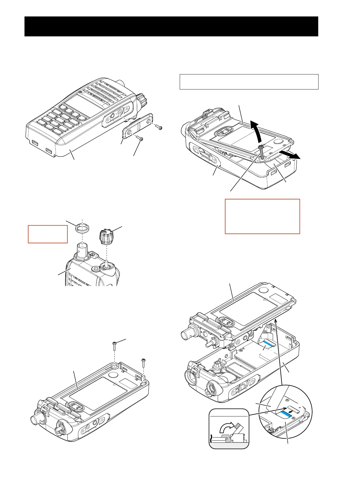
Chassis
MAIN UNIT
FLAT CABLE
Lift up
flat cable
Flat cableFlat cable
Flat cable
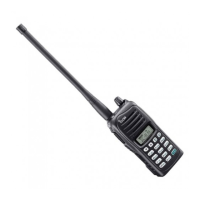
1. REMOVING THE FRONT PANEL
1) Remove the 2 screws from the jack panel ,and then
remove the jack panel from the front panel.
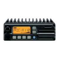
2) Remove the volume knob and antenna nut from the top
of the front panel.
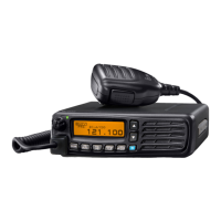
3) Remove the 2 screws from the bottom of the chassis.
4) Screw just the end the M3 screw into the screw hole in
the chassis, and then remove the chassis from the front
panel.
• BE CAREFUL about the flat cable when removing the
chassis from the front panel.
5) Disconnect the flat cable from the MAIN UNIT.
Screws ×2
Jack panel
Front panel
Antenna nut
Volume knob
Remove with;
“ICOM Driver (K)”
(8960000113)
Front panel
Screws ×2
Chassis
Front panel
Chassis
M3 screw (screw thread pitch: 0.5 mm)
The M3 screws are commercially
available.
When ordering parts, the following
parts are recommended.
“PH M3×16 SUS”
(8810000620)
Flat cableFlat cable

 Loading...