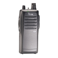
Adjustment for FX-2463 (IC-F11)
ADJUSTMENT
Adjustment No. Adjustment Condition & Tuning Value Ref.No. CK.Point
Preparation Connect the transceiver by cloning cable
(OPC-478) to a PC (IBM compatible) and
boot up the cloning software.
Check points Be sure to use a tester with more than 50
ohm/V internal resistance when making
each test.
Lock Voltage Set the transceiver to the highest
Adjustment band frequency on the TX condition, and set
the LV voltage as follows by means of
spreadable coil L16.
Adj. Freq. Highest. Band Freq.
TX Side 4.0V 4.0V L16
Lock Voltage Set the transceiver to the lowest
Check band frequency, and check that each of
the LV voltage is within as follows.
Adj. Freq. Lowest Band Freq.
RX Side 0.8V~1.8V 0.8V-1.8V LV
TX Side 0.8V~1.8V 0.8V-1.8V
Frequency Connect a power meter or attenuator to the
Adjustment antenna terminal. Loose coupling the ANT
and frequency counter.
Set the transceiver to near the TX greatest
high band frequency and set the unit to TX.
Use adjustment software to adjust the TX
frequency to the values below.
Set Frequency Center Freq. ± 500 Hz ±500Hz Adj.Soft ANT Con

 Loading...